
Arduino PID DC motor position control close loop system
Overview
In this post we will see how we can achieve very precise position control of simple DC motor. We have use Arduino and PID calculation to achieve precise position control of simple DC motor.
Such small project are very much fun to do, you can learn many concept like PID, Close loop system & encoder basic by building this project.
First of all I want to let you brief about what is PID, because this will help you to understand the things further.
PID
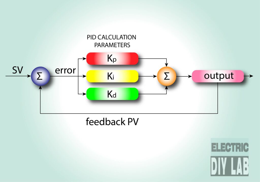
PID stands for proportional derivative and integral calculation
PID is the part of programming, on which a complex calculation carried out by controller and manipulate the Output as per the feedback from the process.
There is 4 key values of PID
1. PV (process value) or feedback
2. SV (set value)
3. Error
4. Output
Basic PID working is as follow, I am not going into complex arithmetic an calculus formulas because I want to keep it simple.
PID try to keep PV as near as possible to SV.
Error = SV-PV Error is difference between Set value and process value
and Output is directly prepositional to Error hence in other words we can say greater the difference between SV and PV greater the Output, if Error is positive output is positive if error is negative output is negative. As PV reach closer and closer to SV the Error get smaller and smaller so on Output also get smaller and smaller, so in this way we get a clean and precise output.
Here is a real life example.
Suppose I tell you to drive a break less car exactly 1 km on straight road
because you don’t have break so the throttle is all you can use to control the car
so you get in car press the throttle and accelerate for a while then release throttle to decelerate and gradually stop at the 1km point.
this is all what you have done we can call it PID control. PID knows how to manipulate output before reaching the SP
Kp, Ki, Kd are the parameters by which we can fine tune the PID controller
those parameter can control over shoot undershoot oscillation.
Suppose a micro-controller drive the car without PID, it will start the car and continue to accelerate until reach the 1km point.
and then release the throttle due momentum car continue to move and gradually stop way beyond to our set point of 1km.
then again micro-controller reverse the car and accelerate as he came back to 1km point release the throttle again same thing happen it continue to move in back due to momentum and such cycle repeat again and again.
you can imagine now it is almost impossible for a controller to stop the car at fixed point with out PID
Below is the visual to understand how PID smooth motion looks.
Video
How it works
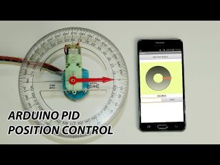
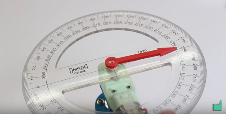
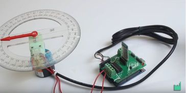
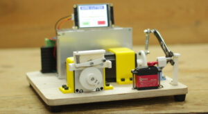
A double shaft simple DC gear motor is connected with shaft of encoder on one side and on other side a pointer is connected this pointer points the angle marked on protractor, encoder is connected with arduino on interrupt pins and DC motor drive by L293D motor IC, a HC-05 module is use to connect our system with android device
When we send angle setpoint from android device arduino receive the data and run the Motor meanwhile encoder sends real time position feedback to arduino as per predefined calculation when encoder pulse matched with requirement it means pointer reach the desire position arduinuo stop the DC motor at such potion. all the process is controlled by PID for smooth and clean motion.
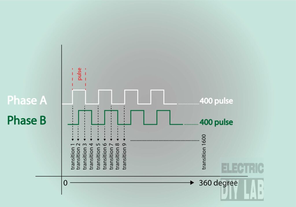
For example here we have used a optical encoder which give 1600 transition pulse for 360 degree revolution, so if we want to rotate pointer to 90 degree so the 1600/360 x 90 = 400 pulse from encoder tells us it moves 90 degree.
Components
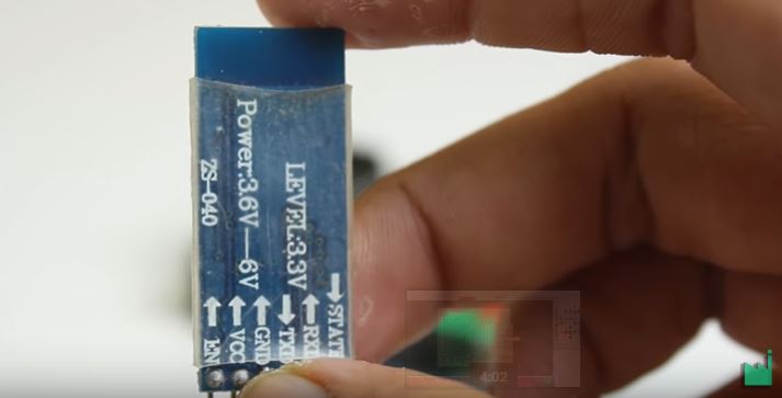
I have used a simple BO motor a optical encoder is connected to its shaft a 360 degree protractor is used as a scale HC-05 bt module is used to connect arduino and android device and a android mobile phone to run android app to send angle set-point to arduino
Below are the link of product in case if you need to buy them
I 3d printed some parts to mound motor and encoder, I also 3D printed pointer you can find the 3D file on the link below.
https://www.thingiverse.com/thing:3221695
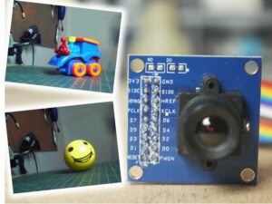
Optical encoder
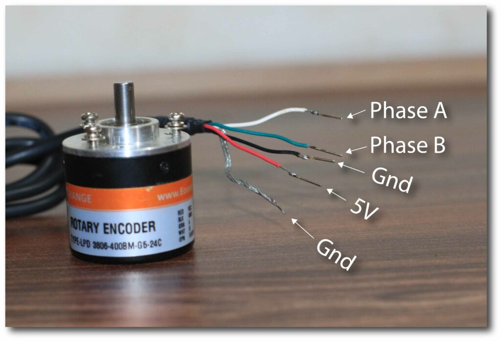
I have used here a 400 ppr 2 phase incremental optical encoder this encoder can give reference of 1600 translation per evolution means 800 transition per phase, we need to connect pullup resistor connected to phase A and phase B because we cannot leave pin floating to avoid any disturbance, in our case we are using arduino which have inbuilt pull up resistor facility just need to activated from code.
 pinMode(encoderPin1, INPUT_PULLUP);
  pinMode(encoderPin2, INPUT_PULLUP);
To know more about encoder please read this post
Circuit drawing
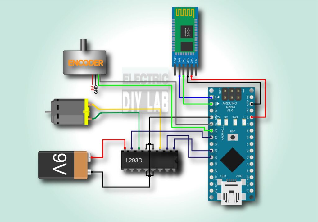
Do the wiring as shown in the image above, encoder green and white wire must be connected to the interrupt pin of arduino which is digital
pin 2 and 3
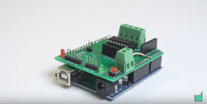
Here I have used a L293D H bridge motor control IC is used to control DC motor it can work on voltage range of 5V to 36V it can handle 1A per channel and peak of 2A per channel
HC-05 BT module must be connected to serial pin(TX, RX) pin 0 & 1 on arduino.
I have used 9V battery to supply power to motor.
Code
Before begin towards coding you must need to install a PID library
an excellent library by br3ttb this library is very easy to use and upto the point.
#include <PID_v1.h>
#define MotEnable 6 //Motor Enamble pin Runs on PWM signal
#define MotFwd  4  // Motor Forward pin
#define MotRev  7 // Motor Reverse pin
String readString; //This while store the user input data
int User_Input = 0; // This while convert input string into integer
int encoderPin1 = 2; //Encoder Output 'A' must connected with intreput pin of arduino.
int encoderPin2 = 3; //Encoder Otput 'B' must connected with intreput pin of arduino.
volatile int lastEncoded = 0; // Here updated value of encoder store.
volatile long encoderValue = 0; // Raw encoder value
int PPR = 1600;  // Encoder Pulse per revolution.
int angle = 360; // Maximum degree of motion.
int REV = 0;          // Set point REQUIRED ENCODER VALUE
int lastMSB = 0;
int lastLSB = 0;
double kp = 5 , ki = 1 , kd = 0.01;             // modify for optimal performance
double input = 0, output = 0, setpoint = 0;
PID myPID(&input, &output, &setpoint, kp, ki, kd, DIRECT);

void setup() {
  pinMode(MotEnable, OUTPUT);
  pinMode(MotFwd, OUTPUT);
  pinMode(MotRev, OUTPUT);
  Serial.begin(9600); //initialize serial comunication

   pinMode(encoderPin1, INPUT_PULLUP);
  pinMode(encoderPin2, INPUT_PULLUP);

  digitalWrite(encoderPin1, HIGH); //turn pullup resistor on
  digitalWrite(encoderPin2, HIGH); //turn pullup resistor on

  //call updateEncoder() when any high/low changed seen
  //on interrupt 0 (pin 2), or interrupt 1 (pin 3)
  attachInterrupt(0, updateEncoder, CHANGE);
  attachInterrupt(1, updateEncoder, CHANGE);


  TCCR1B = TCCR1B & 0b11111000 | 1;  // set 31KHz PWM to prevent motor noise
  myPID.SetMode(AUTOMATIC);   //set PID in Auto mode
  myPID.SetSampleTime(1);  // refresh rate of PID controller
  myPID.SetOutputLimits(-125, 125); // this is the MAX PWM value to move motor, here change in value reflect change in speed of motor.
}

void loop() {
  while (Serial.available()) { //Check if the serial data is available.
    delay(3);                  // a small delay
    char c = Serial.read();  // storing input data
    readString += c;         // accumulate each of the characters in readString
  }

  if (readString.length() >0) { //Verify that the variable contains information

   Serial.println(readString.toInt());  //printing the input data in integer form
    User_Input = readString.toInt();   // here input data is store in integer form
}
REV = map (User_Input, 0, 360, 0, 1600); // mapping degree into pulse
Serial.print("this is REV - ");
Serial.println(REV);               // printing REV value

setpoint = REV;                    //PID while work to achive this value consider as SET value
  input = encoderValue ;           // data from encoder consider as a Process value
 Serial.print("encoderValue - ");
 Serial.println(encoderValue);
  myPID.Compute();                 // calculate new output
  pwmOut(output);
}
void pwmOut(int out) {
  if (out > 0) {                         // if REV > encoderValue motor move in forward direction.
    analogWrite(MotEnable, out);         // Enabling motor enable pin to reach the desire angle
    forward();                           // calling motor to move forward
  }
  else {
    analogWrite(MotEnable, abs(out));          // if REV < encoderValue motor move in forward direction.
    reverse();                            // calling motor to move reverse
  }
 readString=""; // Cleaning User input, ready for new Input
}
void updateEncoder(){
  int MSB = digitalRead(encoderPin1); //MSB = most significant bit
  int LSB = digitalRead(encoderPin2); //LSB = least significant bit

  int encoded = (MSB << 1) |LSB; //converting the 2 pin value to single number
  int sum  = (lastEncoded << 2) | encoded; //adding it to the previous encoded value

  if(sum == 0b1101 || sum == 0b0100 || sum == 0b0010 || sum == 0b1011) encoderValue ++;
  if(sum == 0b1110 || sum == 0b0111 || sum == 0b0001 || sum == 0b1000) encoderValue --;

  lastEncoded = encoded; //store this value for next time

}

void forward () {
  digitalWrite(MotFwd, HIGH);
 digitalWrite(MotRev, LOW);

}

void reverse () {
  digitalWrite(MotFwd, LOW);
 digitalWrite(MotRev, HIGH);

}
void finish () {
  digitalWrite(MotFwd, LOW);
 digitalWrite(MotRev, LOW);

}
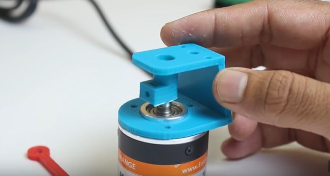

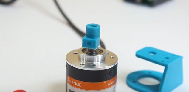
As shown in video and images above first i connect encoder and dc motor with the help of 3D printed coupling and 3D printed mounting bracket, I secured the mounting bracket on encoder with the help of M3 X 10 bolts.
on the other side of bracket I glued dc motor in this way dc motor shaft is directly connected to encoder shaft, encoder shaft moves along with dc motor shaft and continue give position reference to arduino
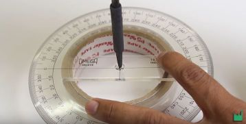
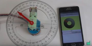
Now I bring a big 360 degree protector and drill a hole in the center so that it can mount on DC motor shaft now I connect a 3D printed pointer on the other shaft of motor this pointer points the angle of motion of dc motor shaft.
I have a PCB available to that I can connect DC motor, L293d IC and HC-05 module and this PCB can work as arduino uno shield and can directly mounted on Arduino UNO.
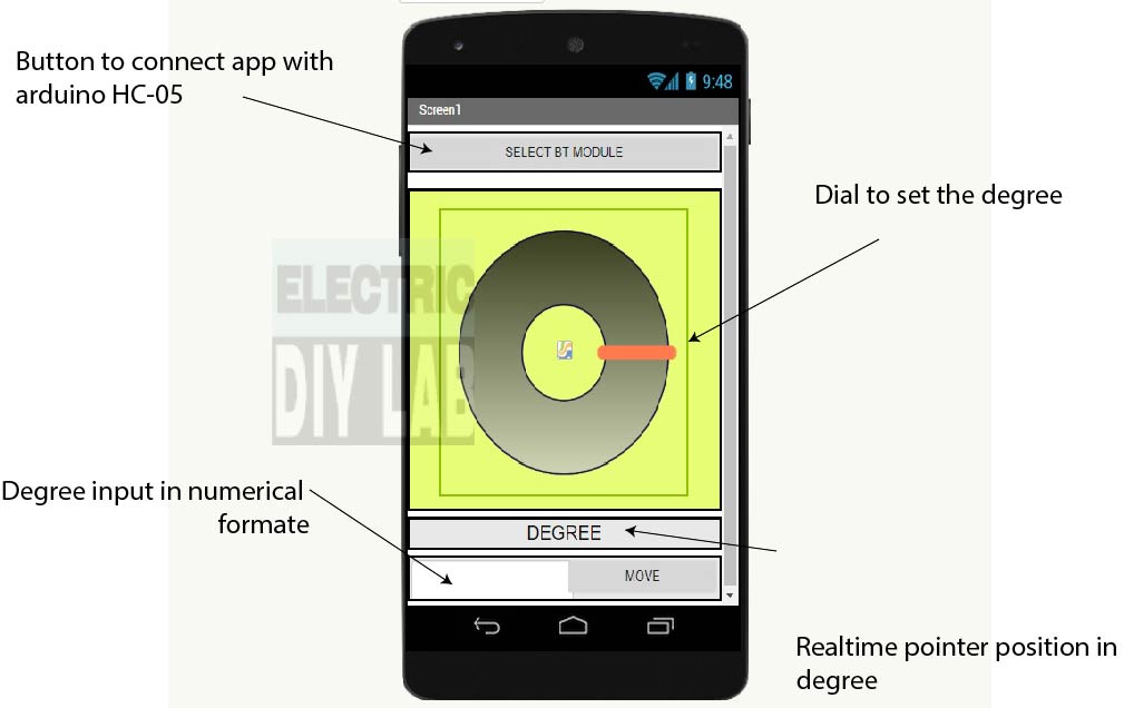
As soon we complete assembly of all component its time to run the project so we need a android device and android app, you can download android app and editable .aia file from the link below
Android app
Editable file
Download the app just do the following thing of android massage pops up to allow install from unauthorized source.
Navigate to Setting > Security.

Check the option “Unknown sources“.

Tap OK on the prompt message.

Select “Trust“.
project is ready when download is complete open the app send the desire angle or move the dial to move the pointer accordingly
hello,
your code was a saviour for me !! thanks a lot for your effort !!
after uploading the code the motor was looking perfectly fine until I have sent degree. it seems very precise and that’s awesome but the shaft keep going back and front in a non-stop motion!
please help!
change some value if “D”
Can I develop this circuit on proteus
Hello Sandeep !
Awesome work, thanks for sharing !
I am trying to read datas from an opticalWheelEncoder, took apart from an old inkjet printer, with arduino, it’s been 3 days i tried out many many different wiring and codes but it returns 0 each time. Maybe you could help ? I wrote a documentation with photos, wiring and code that i can send to you if you had time 🙂 Thanks
wonderful, realy really wonderful, i love this project. thank you Mr sandeep.
thank you !!!!
I am using wiper motor and have to precisely control angle through remote for driverless steering. I need help in this. Can I get in regular touch with you
could you tell me the parameters of the motor (j,b,k,r and L)??
your code isnt working, there are a lot of errors
I would like to ask your help with this project, I am doing it for my course, but it is not working properly, the hc-05 signal is falling, and the engine is shaking when sending the information.
If you can help me solve it I am grateful
smae thing happens with me can u help me pls
bad BT connection are the only possible due to loss connection of RX and TX pin. motor is vibrating all the time or it vibrate when about to reach at desire angle ??
Hello Sir, I’m trying to do your project. But instead of sending the data from mobile app, I tried to send the data from GUI Matlab. But somehow, Arduino cannot store the data given by Matlab. Is there any way to fix that? Do I need to modify the coding at that particular part?
and one more thing, instead of using L293D H bridge motor control IC to control the motor, I used MDD10A. this motor driver doesn’t have enabled pins as it only has PWM and dir pin. So how can I adjust the direction of the motor so that i could get the same output as yours? Sorry for any inconvenience. Thank you. Btw, your project is amazing!
Hello sir, what is the output in data string at application? is it only an angle?
can i use an ac inverter instead of h bridge?
HI very interesting i nwant to do same but in slider for about 3000 mm positioning and home routine can you help?
I actually don’t understand you project will you please explain more about it
can i use stepper motor in this ?
There is no sense to use stepper motor for this project, as stepper motor achieve position control on its on, with step count..
Thank You for this tutorial, but I have one question. Does this encoder know the position of angle if we reset the power supply ?
For example if we set position 90 degree, switch off the power supply and then switch on again – will we know the position of encoder (motor) ?
NO, this is incremental type of encoder it will reset to zero during start up, you need absolute encoder they are capable to give current position value after switching off & on also…
Hello my motor does not motor only it rotates continuously what should be done
probably you are not getting feedback from encoder, try to check encoder alone and see whether it gives data or not you can use serial monitor.
Very nice projekt!!!
I wanna do basically the same, just with an RPi (with Python) and an ADC instead of the encoder.
Should i go the same way about it or are there things to do differently in my case?
Thank you, Unfortunately I don’t have any experience of RPI so can’t help you out in that..
how i use the Editable file
use the software which was used construct the phone application from MIT which is called MIT App Inventor ..
استخدم البرنامج الذي استخدم لعمل التطبيق للهاتف النقال الذي ابتكره معهد MIT
If you need to change anything in app you can use the editable file, you have to visit https://appinventor.mit.edu/ and import the editable file to begin edit..
Are you interested in making a prototype pointer for me?
I need one that is rugged enough to be used on a construction site.
It will rotate a laser pointer that I can attach.
Essentially the same as you have created in this project.
EMAIL . [email protected]
SANDEEP , HELLO
PLEASE EMAIL ME ,
i have a project to you in proffesional way .
Hi could you upload the complex calculus for the PID controller
Hi
I am trying to control the 400 BLDC motor with incremental encoder 2500ppr
and circuit controller. I am using arduino due as my microcontroller. It is getting stabilized but after rotating 20 to 25 turns.
I am new to this field, any help in amending the code to make it usable for my purpose is appreciable.
can you pls share any code or circuit …
I no
you have used finish() function but haven’t used any where on the code.
When will that function be executed ?
setoutput limit function (-125 to 125) comment says that it is the max pwm value to move the motor but the PWM range from 0-100%. so what does -125 to 125 explains ?
0 to 125 for 0 to 100% speed in forward direction and 0 to -125 for 0 to 100% speed in reverse direction
Sir insted of blue tooth I want to control with pc how to write program where to add angle please
Just simply connect arduino with PC run arduino IDE and open serial monitor now enter the angle it works…
Where did all of your other projects go?
It was hacked down few days back, i am starting new from scratch…