
DIY Self Balancing Robot
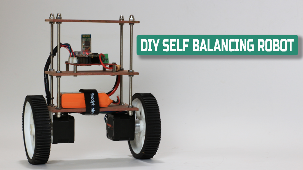
Self balancing robot
Hello friends this post is about DIY self balancing robot in this post I’ll show how you can build your own Self balancing robot.
I have tried to build the project but failed not get results as expected.
but this robot turn out quite good and accurate, though this is not perfect but best as compare to my previous bots.
I have use a custom made PCB, Arduno nano, MPU6050, A4988 driver, HC-05 bt module, MDF board and some hardware to build this self balancing robot,
detail material list you can found further in this post.
Balancingwii firmware and EZ-GUI android app is used in this project to control robot via Bluetooth connection.
So lets begin with some basic of self balancing robot.
Video
Basics of self balancing robot
Self balancing robot is the bot balance itself on two wheels, by constantly correcting its position.
A Gyro sensor is used in self balancing robot, which continuously sends the robot orientation data to the controller.
on the basis of this data controller command the motor to run forward or reverse to maintain the position of robot up straight.
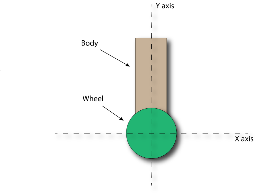
This is the ideal position of self balancing robot, body is perfectly up staring on the wheel
There is zero angle between the Y axis and body of robot.
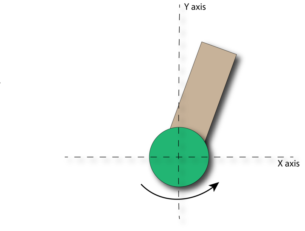
When body tilt in forward direction then there is some angle between Y axis and body.
This angle is detected by MPU6050 gyro sensor, then this data send to Arduino.
Arduino now do PID calculation and command the stepper motor to run in
forward direction to minimize the tilt angle upto zero degree.
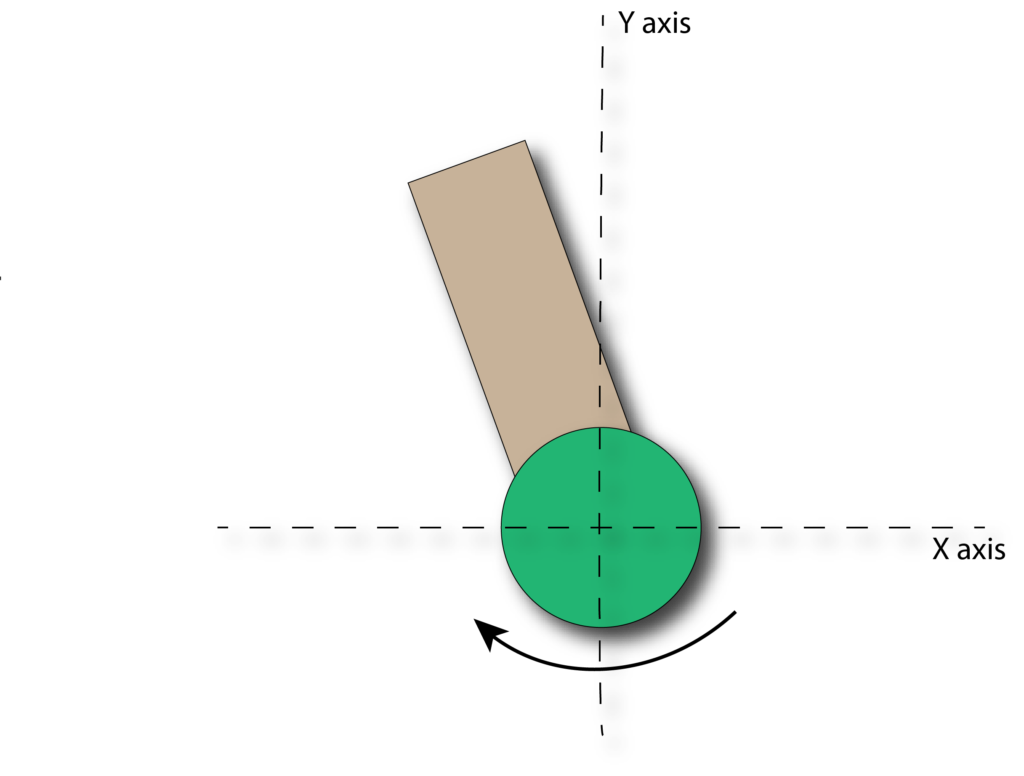
Same thing happens if when robot tilt in backward direction, motor will rotate in backward direction and correct the tilt angle to zero.
The bot in continue running motor forward and reverse more then 400 times in second so its looks us like robot is stable at its place.
Components Required
- Arduino Nano…………………………….1 no.
- MPU605 Gyro sensor……………….1 no.
- Nema 17 Stepper motors………….2 nos.
- 100mm Wheels…………………………..2 nos.
- A4988 Stepper driver IC…………..2 nos.
- HC-05 Bluetooth module………….1 no.
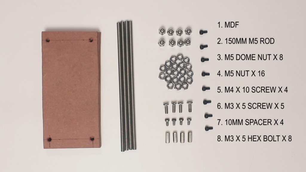
- 4mm MDF board.
- 150mm M5 threaded rods——–4 nos.
- some nuts and bolts
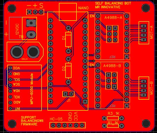
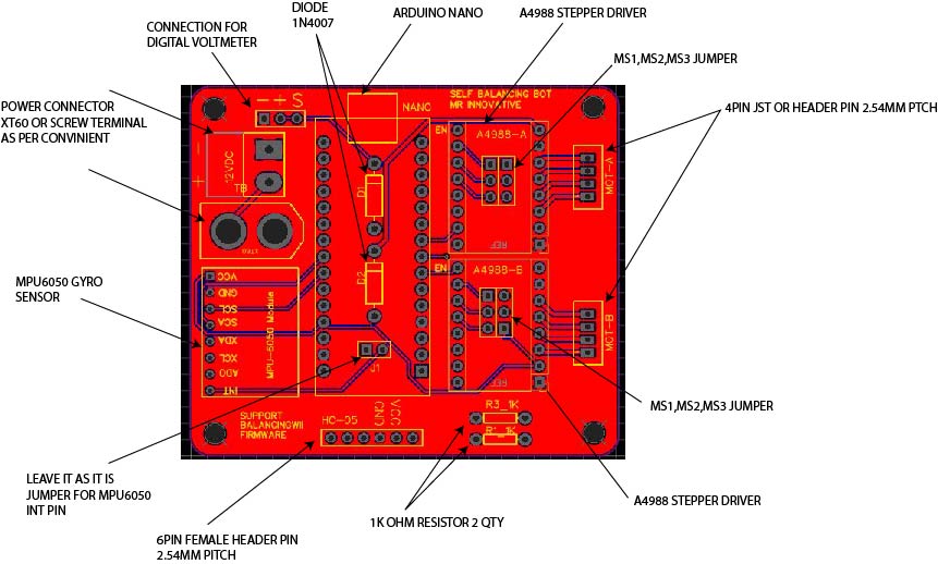
DIY Self Balancing Robot Electrical drawing
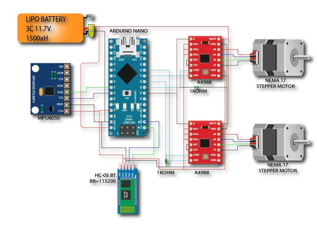
Above image is the circuit drawing of self balancing robot.
I have prepare a PCB also you can download the Gerber file to order PCB or you can also edit the PCB in easyeda platform.
https://easyeda.com/sharmaz747/self-balancing
Note :- KINDLY CROSS CHECK ON YOUR OWN BEFORE ORDERING PCB..
The basic and minimal connection you must needs are as follow.
I2C:
- A4 – SDA
- A5 – SCL
Motor driver pins:
- D5 – STEP1 (PORTD 5)
- D6 – STEP2 (PORTD 6)
- D7 – DIR1 (PORTD 7)
- D8 – DIR2 (PORTB 0)
- D4 – ENABLE (for both)
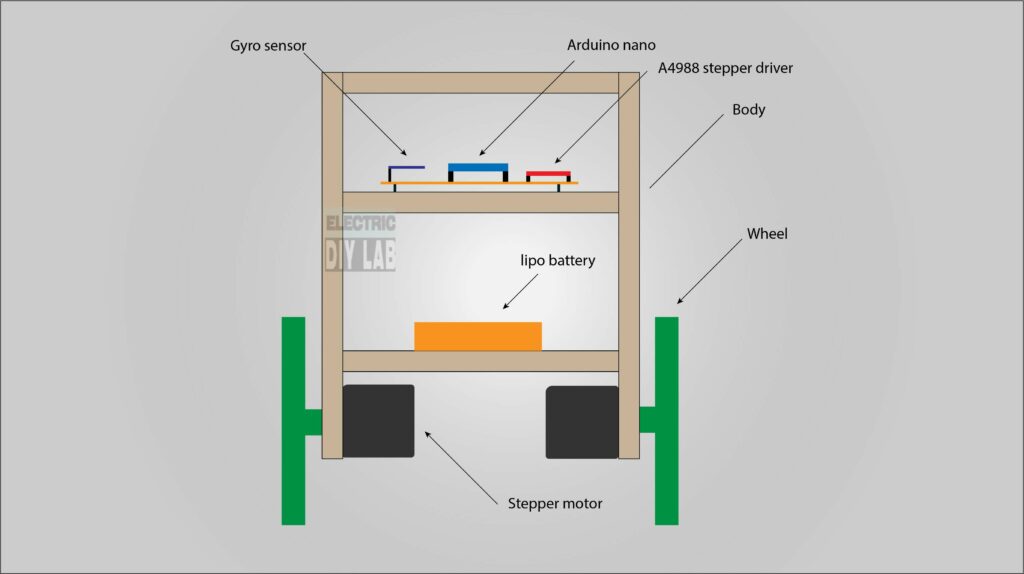
Robot construction
Below is the basic construction image of self balancing robot
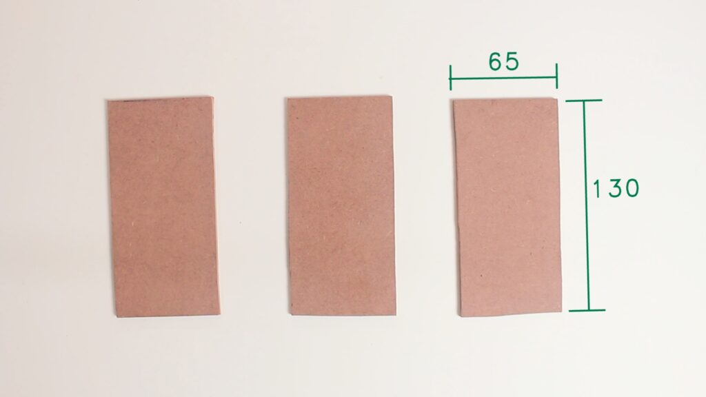
I have cut three pices of size 130 x 65mm
from MDF sheet of 4mm thick
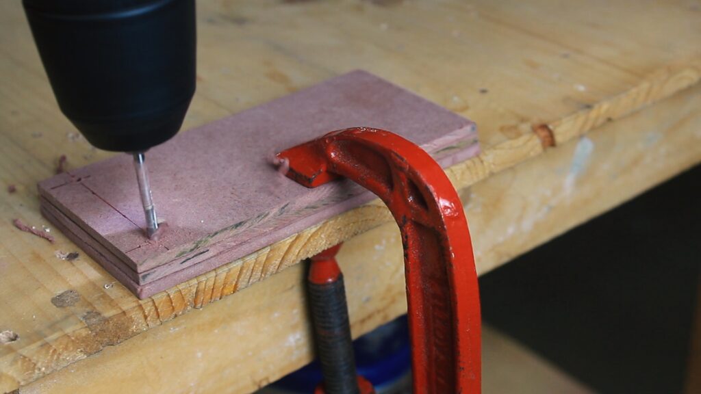
Here I drill some holes to mout stepper motors and insert M3 rod through all three MDF board.
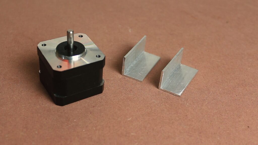
Then I cut two pice of 20 x 20 mm aluminium angle of 42mm in size, this is used to mount stepper motor with platform.
Now I use some hardware to assemble the body of self balancing robot.
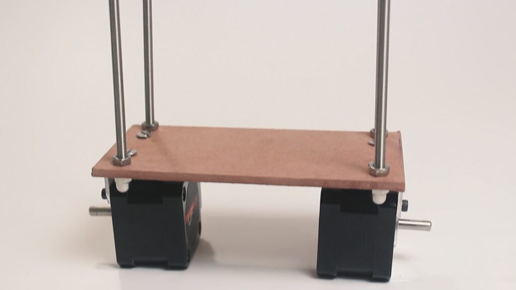
Here I have inserted M5 rod to the base platform and mounted nema 17 stepper motor with the help of 20x20x42 aluminium angles.
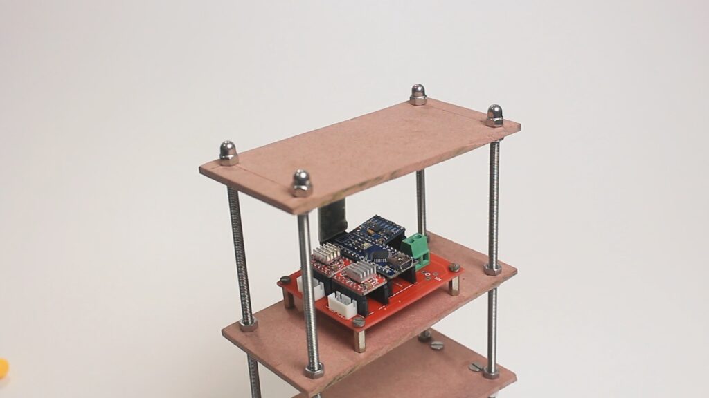
Now I place the middle and top platform on M5 threded rod and fix them with M5 nuts.
And place PCB on the middle platform on 10 mm spacers.
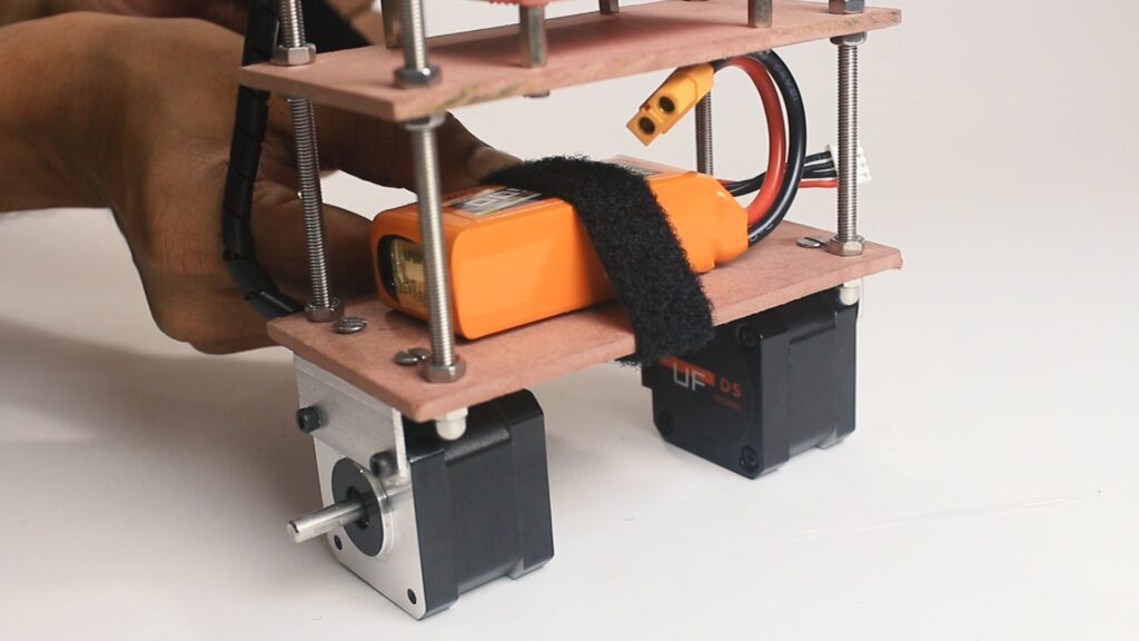
1500mah 11.7 V lipo batter is placed on base platform and hold it on place with a belt.
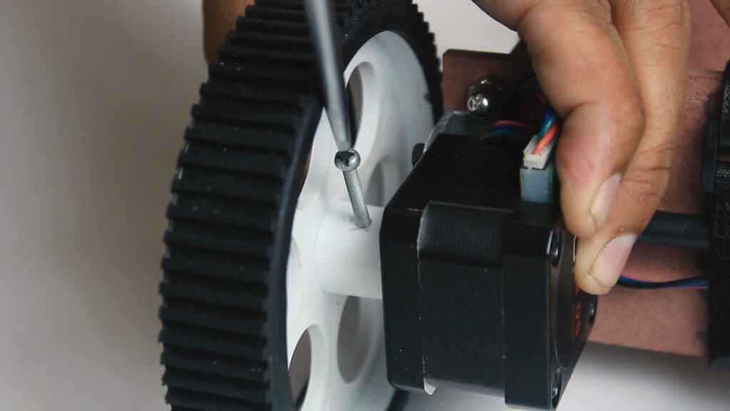
Now finally I secure the wheel on the shaft of stepper motor and tighten it with M3 bot.
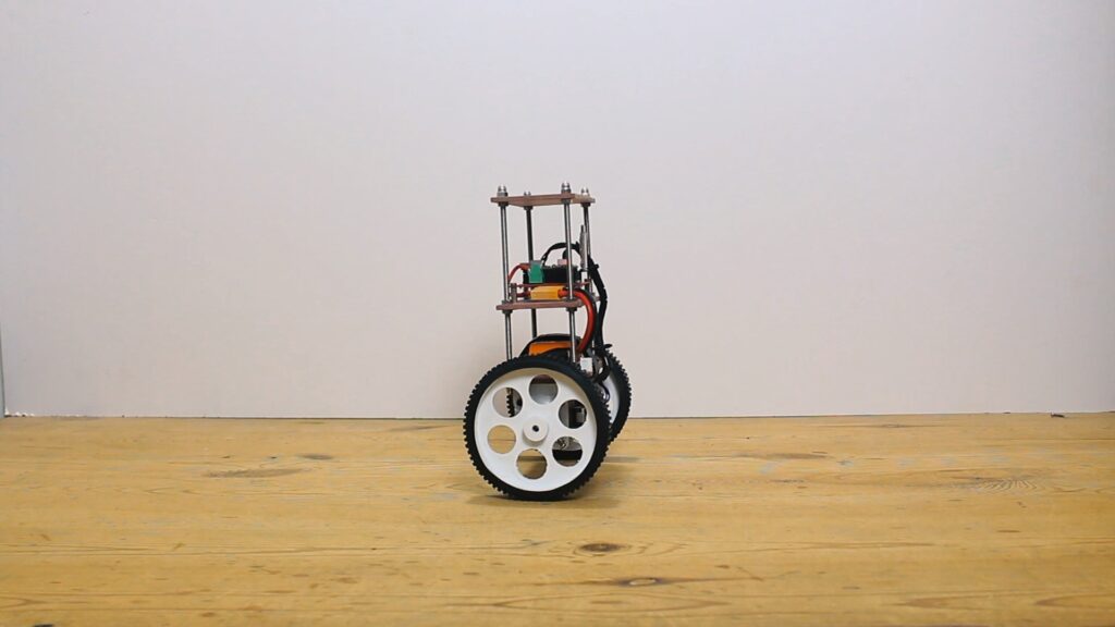
In this way our robot assembly is completed.
Now we can move towards the programming of self balancing robot.
Programming
Download balancingwii
To start programming arduino first we need to download a firmware for balancing robot called balancingwii.
this firmware is based on Multiwii firmware used for quad-copter and multi-rotor flying drones. you can learn here more about Multiwii.
special thanks to Mahowik who develop this firmware.
Download the firmware balancingwii by clicking here, now click on green button clone or download.
The firmware will downloaded in your PC in ZIP format.
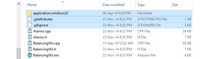
Now unzip the downloaded file, open the newly created folder and delete that three file highlighted in image, this we not need at all.
also the name of folder containing balancingwii.ino file both must be same other wise you will get compiling error.
now open the balancingwii.ino file in arduino and compile the code and upload it with out changing any thing.
Don’t forget to turn off BT module before uploading the code.
If your MPU6050 orientation is different then my one you need to change this line in config.h file
You can change here PITCH to ROLL
#define CURRENT_AXIS PITCH // possible to choose ROLL or PITCH axis as current.
By default mostly all HC-05 BT module came with default 9600 baud rate.
but for this project note that the baud rate of your HC-05 BT module must be 115200 other wise you cannot able to connect with android app
You can change the baud rate of HC-05 bt module via AT command search it on google you’ll get many tutorial about it.
/* This is the speed of the serial interfaces */
    #define SERIAL0_COM_SPEED 115200
    #define SERIAL1_COM_SPEED 115200
    #define SERIAL2_COM_SPEED 115200
    #define SERIAL3_COM_SPEED 115200
If you feel your robot is less responsive then you can try to change this setting in config.h file, but be remember the values must be in constraint.
 #define MAX_SPEED           350  // should be <= 500
 #define MAX_TARGET_ANGLE    130  // where 10 = 1 degree, should be <= 15 degree (i.e. <= 150)
#define MAX_STEERING        90   // should be <= 100
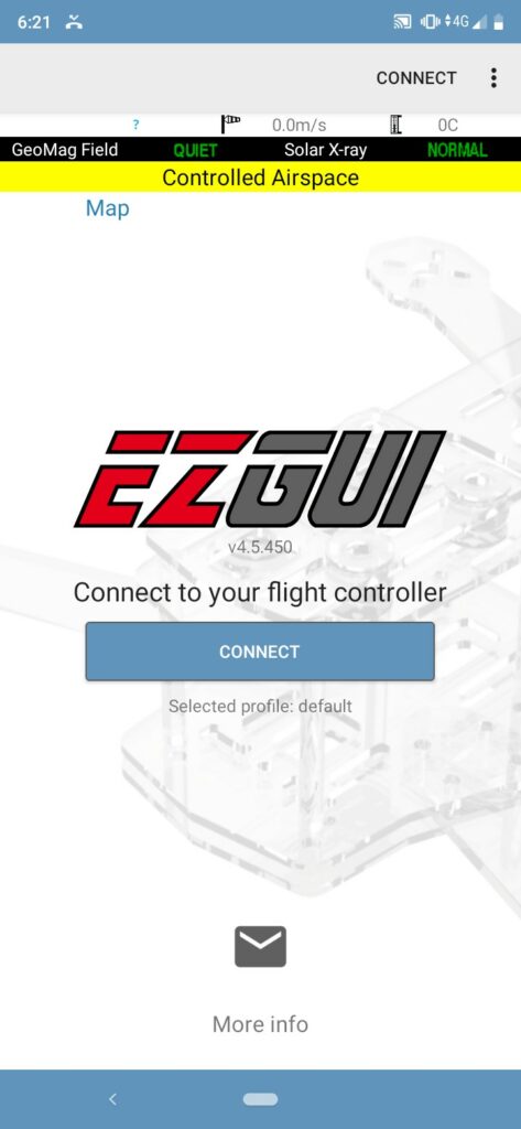
Android app
EZ-GUI app is we going to use here you can learn more about EZ-GUI from here
EZ-GUI app is available to download from play store for free by click the link below or by scanning the below QR code.
https://play.google.com/store/apps/details?id=com.ezio.multiwii

App configuration
Open the downloaded app and click on the three dot at top right corner of screen
Click on the settings.
Select on BT Device to select BT module
now click on NEXT button
Now select the firmware “Multiwii 2.40” from the list and click next next until you reach the home screen.
Click on “CONNECT” button to connect with bluetooth.
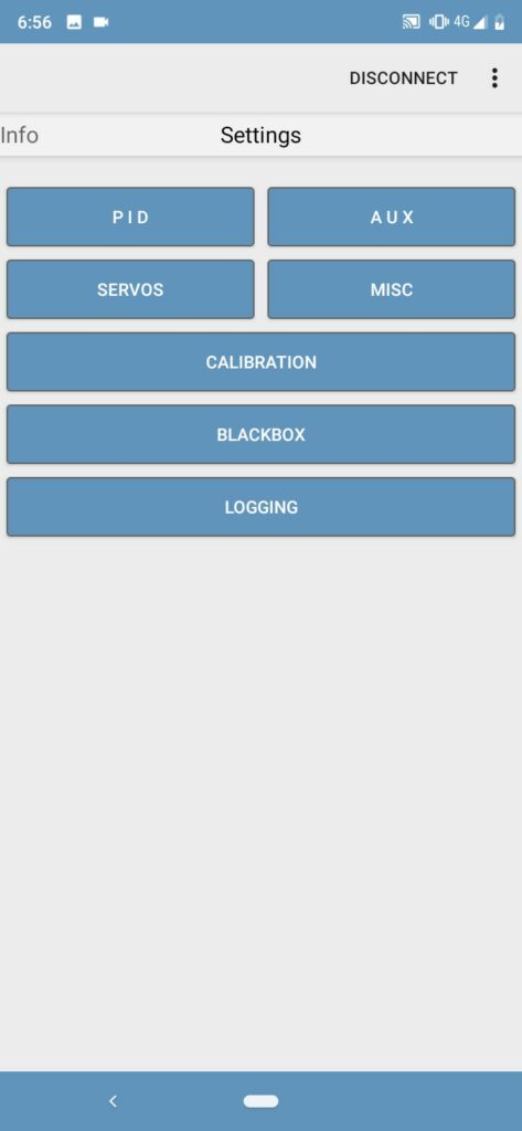
Clink on “AUX” button
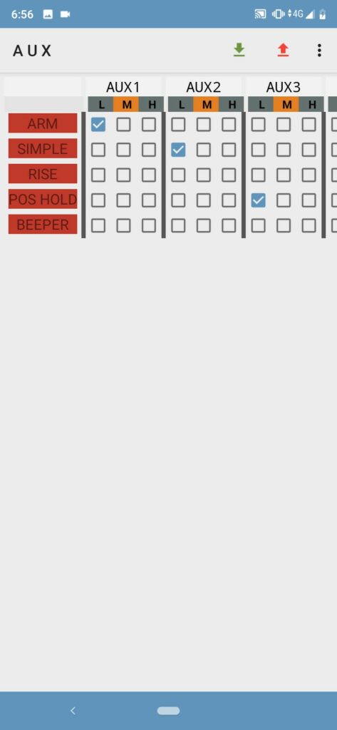
Tick mark as shown above.
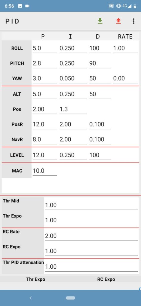
This is my PID settings.
It is not compulsory that this PID settings will work for you bot each and every bot is unique.
PID is depends on bot desing, center of gravity, wheel size, motor type, and more.
try different setting you will surely get sweet setting after some trials.
now back from this screen, and click on three dot at top right corner and go to “advance” and then go to “Untested” and then click on “Model control”
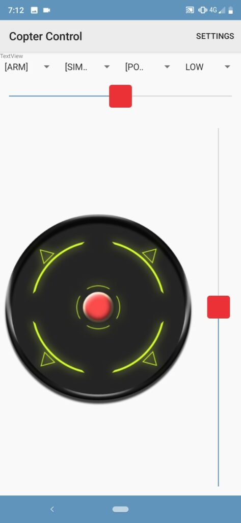
Now this is the screen to play with you bot, you can run you self balancing bot from the joystick,
play with this screen try different settings to learn more.
In this way our DIY Self Balancing Robot is ready to play. enjoy..
if you have any question please ask in comment section.
Sandeep, I am unable to upload the code.
You say, “Don’t forget to turn off BT module before uploading the code.” Please tell me how I do that.
Remove Bluetooth module while uploading code
Hi , I am Jacky. My robot can not balanced by itself. Which parameter of PID I shoulid adjust? Otherwise, When the robot start, the motors can not running to feedback the robot real time, need some time to move.
Which mean about the (only ms1 and ms2 connected in 5V and ms3 floating)? Is It means the ms3 not need to connect the 5V?
Thanks much Sandeep for this fantastic video. I am stuck on the wheels. The link here to purchase wheels takes me to Flipkart, which doesn’t sell outside of India (I am in USA). Do you know of another vendor that sells the specific (100 mm diameter, fitting these stepper motors) wheels? I have not been able to find this online. James
You can try this one..
https://www.amazon.in/Invento-Plastic-Robotic-Durable-Rubber/dp/B07PCH8CNZ/ref=sr_1_10?dchild=1&keywords=100mm+wheel&qid=1596465690&sr=8-10
Thanks for posting this project. Is this LiPO Battery good 11.1V 5200Mah? thanks.
Its good
Can i use 17 hs4401 with 1.7A on a4988d drivers or i need a motor with lower current
Can i use lithium ion batteries 18650 in replacement of a lipo battery
Yes you can use that stepper with a4988 without any doubt, but I recommend you only use lipo battery because it have high current discharge capacity, this will give best performance to robot, I suggest you not to use lithium ion..
Hi, got the robot built and working just fine thank you. Is it possible to
use model plane radio control Tx and Rx2 for control and where would I connect it.
Cheers
Robert
HI sorry to say you that I don’t know about this because I haven’t used it
Thank you for sharing your Sandeep knowledge. I’m going to carry out the project, I already have all the components, I’m just waiting for the PCB to arrive. I only have one fear: download the Gerber file without modifying anything, I hope this is correct, and I would appreciate if you can help me in the assembly and calibration process. I made a 3D printed bases https://www.thingiverse.com/thing:4393944 for the sth-39h112-06 stepper motor.
First of all, Thanks!
your frame is very nice..
Hi sandeep! Thank you very much for your hard work. Thanks to you, I can study new things. But while studying, I ran into difficulties.
I downloaded the Aduino programming folder you uploaded, but there was only a ‘c++’ file There was only one Aduino file. When I opened the Aduino file, the coding did not exist and only said what was updated.
I wonder if I have to open and copy the ‘c++’ file to a visual studio and then copy it to Aduino programming. I leave a comment because I’m confused. Thank you very much for reading all the long sentences. Have a great day today.
watch 10:00 time stamp in video here you get your answer
Hello Sandeep, fine job i like very well thank you
can i use an arduino uno instead of an arduino Nano and apart from compiling in uno, is there a change to the program?
Thank you and good day
yes you can use
Finally I managed to successfully implement this robot, congratulations to the author! I had difficulty understanding the PID adjustment, but in the end, after many tests, I realized that it would not be necessary to change any of the data reported (based on the video values) the critical point, in my case, was to leave the resolution of the step in eighth step (only ms1 and ms2 connected in 5V and ms3 floating), with the sixteenth step the robot was able to balance itself but it was not in a fixed position, it made an oscillation amplitude of about 40 cm. It was necessary to change the transmission rate of the HC-05 to 115200 by AT commands, but it was fine. To make the cursor go back to the center in the app: settings => check the “back to MID” fields. Do not forget to use an electrolytic capacitor (100 uF or more) between the Vmot and GND pins of the A4988 driver, unfortunately, during the tests, some were burned because I did not use this capacitor. Any questions I will be happy to help you by email [email protected].
Nice to hear that ?
Hello, your work is incredible and very nice. So I decided to make one.
I replaced the MDF with parts in 3D printing. I made the circuit following your electrical drawing. I did different test programs for my two engines, the MPU 6050 and the HC05 at 115200. Everything works separately correctly.
I followed your very good video on the use of EZ-GUI. Communication is carried out correctly. However, in the end, nothing happens and no command by the application is made. Could you help me and give me an idea to finalize my robot.
Thank you beforehand. Bruno
Have you done the calibration process ?
Thanks for a very quick response.
Yes, I did the calibration.
Then I have an audible message “Console deactivated”. Is this normal
What is the setting of the microsteps of the motors?
Buad rateAT command must be like this
AT+UART=115200,0,0
Please cross check it once
Hello sandeep,
How many volts does the Stepper Motor have?
12v
Thank you very much, I have assembled one and it works very well.
Hi
Can i use hc-06 instead of hc-05??
What is the meaning of 115200??
I dont know about HC-06, and 115200 is baud rate of comunication
Hello sir ! Thanks
My self balancing robot is ready .
But when i connect it to phone with ez gui , it connects successfully but when I’m going to AUX settings application show me something like this ….. ” No inough information”
And application says that no data receive.
Please help me
Please…
Hi. First of all, thank you for you share your idea with us.
I have question about if I use l298n moter driver instead of A4988.
Could you tell me which part of code do I need to change.(and more thankful if you tell me how to change it)
Thank you 🙂
L298N can’t work with this firmware.
I meant if i should solder for GND pins of the drivers, bt, mp on one end, wich is gonna be on the nano gnd
sir can i use 11.1V lipo battery?
Helllo sir! i would like to thank you for that amazing project then I wonder if I can reproduce this project using a STM32 Nucleo-32GO31k8 board also using the same components including the android application to control the robot.
yes you can use
sir can i use 2200 mah lipo battery??or should i use what is given in the schematics?
yes you can use
does it require any more coding,rather than the one you mentioned in the video
no any other coding required
Boa noite amigo, a dias venho tentando construir um robo baseado no seu projeto, porem o sketch da erro ao compilar no Arduíno Nano e não sei o motivo. O que tenho notado é que aparece dessa forma BalancingWii.ino mais não com o simbolo do Arduíno, é um projeto muito bacana e eu não queria desistir mais nãos sei o que fazer. Se tiver uma solução para meu problema eu agradeço.
Hello Sandeep,
thank you for all your help. I am having trouble with an error reading on the GUI app. “12c errors”. all wiring is correct (SDA=A4, SCL=A5). sometimes I can start the calibration before the error comes but usually right when connected it starts beeping and flashing the error. I have run a basic data output on the MPU and it seems to be working properly. Would you be able to suggest anything? Has anyone else run into this problem?
Thaks for your time.
Hello. I’m curious what would change if you changed the position of the parts of the robot. Like if you put the Arduino or battery between the motors. This would make the robot much lower profile, but would it cause any issues with performance?
Nothing to change anything in firmware rather than PID values, but if you change the orientation of MPU6050 sensor then need some change in firmware ..
Before testing the circuit, I tested all the elements.
Now I measured it again with a multimeter
Current and voltages passing through are correct
But motors still dont turn.
How can I solve this
hello,
I’m wondering if you can run this on a Mega2560?
When I upload the sketch I get…
Output.cpp:162:13: error: ‘DRIVER_PIN’ was not declared in this scope
pinMode(DRIVER_PIN[{i}],OUTPUT);(5)
^~~~~~~~~~
Output.cpp:164:3: error: expected ‘;’ before ‘}’ token
}
^
exit status 1
‘DRIVER_PIN’ was not declared in this scope
Would you please be able to help?, I live in a very rural area and am waiting on a new nano, I just want to make sure all works before it gets all put together.
Thank you.
No you can not use mega, firmware design for nano only
did i damage my gyro sensor while soldering header pins at the gyro board??
could this be the issue
but the led indicator is lighting up after all this but giving no readings…
please double check SCL & SDA connection.
checked them
A4 —> SCL
A5—>SDA
5V—>VCC
GND—>GND
these are the connections, i have checked it multiple times
Your connection is wrong, A5—> SCL & A4—-> SDA
hello sandeep , btw i have to tell u that the project i awesome but i am facing a new kind of error, .
i did all the connections , motors are also spinning but when i keep the bot vertical after caliberation the motors don,t stop spinning they stop to spin when i make the gyro sensor at differnt orientation but if i do that and tilt the bot in opposite directions the motors dont change directions rather they change directions when i rotate the sensor full 180 deg. in a large circle radius ,
plz help me out here
I hope you MPU6050 gyro placment orientation is exactly same as mine, if not go to the config.h file in balancingwii folder
find the below line and twerk it and observe the result hope you will get your setting by doing this.
#define CURRENT_AXIS PITCH // possible to choose ROLL or PITCH axis as current.
//#define INVERT_CURRENT_AXIS // invert current axis sign, i.e. instead of turning sensor board
sir i also have a doubt , i saw your self balance robot video that u made 1 year back and i that u gave a YABR_HARDWARE_TEST file , i made all the connections accordingly and ran that file on my gyro sensor and it showed me in serial monitor that “no i2c detected”
does this mean my gyro is not working???
ps : last night my gyro was giving readings on mpu6050_raw code and today it is printing every value as 0 , and my gyro led indicator is lighting up, but still this is happening , i bought a new sensor and attached the header at breakout board and tried that out aslo but still it is the same
is my gyro defective ???
Good day and thank you for the totorial,
I am just about to solder this project up (without PCB board) and I noticed that on your board there are provisions for two diodes. where are they placed on the project or are they only used on the PCB?
Thank you for your time.
diode is for protection from cross polarity connection you can proceed without using them, you can refer this drawing https://electricdiylab.com/wp-content/uploads/2019/09/Self-balancing-robot-circuit-drawing-1024×759.jpg
can i use 28-byj stepper motot instead of neema 17 stepper motor
no you can’t
Dear sir please send me final code
sir can you tell me what should be the the parity bit and stop bit when changing the baud rate from @9600 to @115200 .
please help , its urgent.
it must be like this 115200,0,0
Hello,
Can you write down the steps of the calibration?
Thank you.
Hello,
Can you write down the steps of the calibration?
Hi sir!!!
code is not uploading in the nano. i tried many times but here is the error that it is showing. please update the gerber file, i got wrong one printed!!
HERE IS THE ERROR:
An error occurred while uploading the sketch
avrdude: stk500_recv(): programmer is not responding
avrdude: stk500_getsync() attempt 1 of 10: not in sync: resp=0x66
avrdude: stk500_recv(): programmer is not responding
and so on till 10 times of attempting.
Dear
Thanks for sharing this project to us.
I have a little problem.
I will connect my bot to the app but when I click on connect the app said wrong MAC address.
What can I do to fix it ?
Hi, thanks for the step bye step.
I need ask something about the circuit, and please , apologize me if it’s a fool question , but, in the circuit I can’t see the connection beetwen the resistor and the GND or the step pin of the motor driver, or the connector in the HC-05 .
thanks.
Hi
I found out that there is nog power to the bluetoothmodule, but i saw in the commants that this is already noted. I want to know if you can use the bot just for balancing without the app. I saw that there are default PID values. But my motors juist vibrate without rotate. I saw also in the comments that you have to calibrate it. But I will use this for a project in school. So can I use you’re bot without the app ?
hi, I found out that the bleutooth module doesn’t get power. I connected this pin with the power on the a4988. I have also a question. Can you use the bot without the app, just for balancing ? My moter makes noise but istn’t move. I have read in the commands that you have to calibrate before it wil work. I saw in your code that you set a default PID values. So I wanted to know if I can use this project without the app.
Thanks
Hello, i want to ask you if the pcb is working properly that you provided in the description.
How to interface this program to arduino mega 2560????
Hi ,
Thanks for the good project
I am doing this project and enjoyed it really but I have a PCB used for the CNC using nano , any motor driver 4988 or 8825. But step and direction pins are different than the sketch
I have 17HS08-100S4 motors with DRV8825 drivers and this PCB owns its I2c and blutooth place to use.
I reviewed the software for making it compatible to the card pins for 3 days but output.CPP to config to output again to change all the pin statemnts
I need help in that , would you ?
Thanks
Hi man I have a problem the step motors not moving, They produce noise but no movement what so ever? can you help me figure this out, I have spent hours adjusting the PID settings in the EZ GUI, but no noticeable results.
Thank you
have you calibrate the bot ?
Yes I have. I guess my question is, how did you set up the pid settings, did you set it up manually or did it show up for you after the calibration?
Hello, can you please send the old gerber file, or maybe if u fixed the new pcb, because there is short on +5v and grond.
hi sandeep ,
i follow yours very well and got fun really
i am trying to do that bot , i did the same design except i got a dummy nano CNC shield v4.0 from another project to be used instead of alot of soldering and also it has i2c and serial for blutooth , it already assign different pins for stepper motor step , direction and enable signal also
i got the firmware of balancing wii , but iam trying to modify to got compatible with the mentioned pcb
too much code i should review to get it comptent with the card , wouldyou help in that
thanks
hola amigo ya tengo armado todo las conecciones y estructura, pero los motores no tienes estabilidad yo los calibro conecto a bluetooth y no tiene control de si— como puedo hacer q se estabilice ?
[email protected]
Hello sir. Before thank you for this project.
But i need help. My ardiuno gives me error.It says that
C:\Users\BAYARK~1\AppData\Local\Temp\ccXhnrcS.ltrans0.ltrans.o: In function `main’:
C:\Program Files (x86)\Arduino\hardware\arduino\avr\cores\arduino/main.cpp:43: undefined reference to `setup’
C:\Program Files (x86)\Arduino\hardware\arduino\avr\cores\arduino/main.cpp:46: undefined reference to `loop’
collect2.exe: error: ld returned 1 exit status
exit status 1
Error compiling for board Arduino Nano.
🙂
you folder name must be same as .ino file name, remove master if written in folder name
I have the same problema…
Can you help me pese?..
have you solved the problem?
hey good project, i have followed your tutorial and tried to make my own but i am facing issues
i have change the baud rate of bluetooth to 115200
i havent calibrated anything else
i put the pid value as shown and i understand that they are unique but in the beginning i put them just to get a feel of the response of the bot
my problem is that the wheels just spins in 1 direction and rarely it looks like wheels might be stabilizing
my id is [email protected]
can you help me asap??
You must have to first calibrate the bot by placing it on flat surface, without calibration bot doesn’t understand what is up/down/right/left position.
after calibration the wheel movements make some sense, unless until it was random.
I was righht in my conclution, the BT needed power, and soldering another + wire, it now have power, the PCB is not correct made, u need update the files and correct them..
Yes I have noticed it now you need to add a jumper for +5V from arduino 5V pin to BT module vcc pin, I’ll update it thanks for let this know..
np. But i still cant make it work at all, the software aint showing correct on mobil, i dont have the same, even i use the QR code, allso the stepper just spin, and nothing more, even if i flip the board with gyro, nothing happens
Can you give me your mail so we can share some images to solve problem
[email protected]
well, if u look at board, i think one line is missing for either + or -, the BT dont get enoouh power or something, the led is very faint..
i havent calibrated anything?
Damn this project pisses me off, i got the boards today, and i follow instructions, all the right components, guess what, it aint working, the led on BT, its faint red, i tryied with 3, and its the same..
when turning power on, the stepper motor just spins, dosent matter if i tilt the board, nothing change..
Have you changed the default baud rate of BT to 115200
Stepper motor spins randomly until you do calibration of bot
What do I do with the ms1,ms2 and ms3 jumpers??
What stepping resolution do I choose ??
I have shorted all of them (MS1, MS2, MS3) if you found motor skipping steps or generating less torque you may only shirt ms1 & ms2
Hello sir Firstly
I thank you for you share this Project with us .
However I can’t compile this Project in arduino.
It gives me error.It says that C:\Users\Useer\AppData\Local\Temp\cc6yuTgb.ltrans0.ltrans.o: In function `main’:
C:\Program Files (x86)\Arduino\hardware\arduino\avr\cores\arduino/main.cpp:43: undefined reference to `setup’
C:\Program Files (x86)\Arduino\hardware\arduino\avr\cores\arduino/main.cpp:46: undefined reference to `loop’
collect2.exe: error: ld returned 1 exit status
exit status 1
Compile error for Arduino Nano card
no headers files (.h) found in C:\Program Files (x86)\Arduino\libraries\jrowberg-i2cdevlib-f89153
Can you came online on TeamViewer
Yes, I am online teamviewer at now. I send my ID to your gmail
Not received yet
Hello sir, I use Arduino Uno and A4988 Driver for motor. I upload code in UNO but Motor is not working but when i use different code for testing purpose, Motor is work so what is the problem??
By just uploading code to arduino motor will not supposed to move, request you to read completed post to clear some basic doubts.
I implement all the step like calibration, auto tune, pid implementation. Still motor is not working.
hey sir, can we use adruino uno and Ln298 driver for motor ?
do we need to can the codes for the driver circuit
plz reponse fast
no you cant use it at all….
i have followed this instruction, and used the QR code..
cant make this work, the app is not like the one on pictures, allso stepper motor just vibrate like crazy..
Hope you have downloaded correct app, you must have to do calibration before …..
my baund rate is 115200 only sir
HI sir , project is very gud i have done all hardware connections perfectly and program was also compiled and uploded and ezgui app installed and bluetooth is connected but
AT SEETINGS AUX WAS EMPTY AS NO DATA RECIEVED can u plzz give me a solution sir.
Sir I need the Gerber file of the circuit ,in the given link i can’t download it
My mail id:[email protected]
https://drive.google.com/open?id=14-g_mk-J-riYdHKRvjtMzBiXAvIWAYuq
Hi Sandeep. Please could you tell me how you derive the 5 volt supply for the Arduino, Bluetooth and Gyro module? The circuit diagram shows these modules connected directly to the 3S LiPo batter which will surely cause them to fail? Am I missing something??
Lipo battery supply power to arduino through Vin pin and GND pin ans all rest 5V modules gets power from arduino.. refer circuit drawing
Thanks Sandeep. I have never used a Nano before and had no idea that it has a voltage regulator onboard!
I’ve sent the screenshot to your mail
not received yet send it at [email protected]
After connecting to mobile app..via Bluetooth…12c error is coming .we have checked the connections of mpu 5060 ..but the error is same.
Can you show me some screenshot of the error
Sir those are SCL&SDA connections are good but same error was obtained plz help sir
Sir those connections are in correct position . plz tell me about the stepper motor connections to driver sir
hi sir after it connect via app and set pid values and i go to advanced untest it can show notifications like “WARNING ERROR 12C” what it means? What can i do
Check your SCL& SDA connection this is the I2C communication error. Of mpu6050
Hi, congratulations for the project. I have a question, if I use smaller wheels do I have to change some parameters? is the functionality affected?
Hello, you don’t need to change anything in CODE
to achieve best performance only you need to set PID parameters
Hi,
the outline drawing: DIY Self Balancing Robot Electrical drawing, (Arduino, Nema17 …) is in very good quality printout. With which program did you create this overview? Thank you for your response!
Thank you last question can I use DRV8825 stepper motor driver
Yes you can use DRV8825
Can I use arduino Nano in this project
All Done Connections Clear
But Bot Not Responding
Good evening sir
please i have a problem can you help me?
after connection with the HC-05 an error message appears
“Warning no data received”
when I click on the “AUX” button, the AUX1 AUX2 AUX3 tables do not appear, but a message appears in the middle “Not enough information”
please help me
Please note that the baud rate of your HC-05 BT module must be 115200 other wise you cannot able to connect with android app, search on google how to change default baud rate of HC-05 bt module via AT commands
Yes you can use arduino UNO
Can we make this one using matlab simulink
No idea bro..
Do you have a link of the tire you used for this project? (Or the brand)?
Looking forward to trying this out!
This are the wheel I have used
https://www.flipkart.com/techwiz-robot-wheel-100mm-dia-x-20mm-wide-automotive-electronic-hobby-kit/p/itmeza7vvtxehdeu
Thank you for your contributions.
I will ride this bot.
Can you tell me the engine characteristics.
Voltage
Pair
Degrees
Mold
I imagine that with the HC-06 it will work well
thanks again
greetings from Barcelona – SPAIN
this is the same motor I have used but of different make.
https://www.omc-stepperonline.com/nema-17-stepper-motor/big-sale-nema-17-bipolar-1-8deg-26ncm-36-8oz-in-0-4a-12v-42x42x34mm-4-wires-300mm-length-cable.html
okay
Thank you
Hi,
Great project and thanks for sharing. I want to make my own and I was wondering if the PCB has been updated? I ask because I noticed the comment that someone made where you answer “Yes I have noticed it now you need to add a jumper for +5V from arduino 5V pin to BT module vcc pin, I’ll update it thanks for let this know..”
So just wondering if it was updated? Thanks
Yes it is updated..