
How to make Arduino mini CNC plotter machine
How to make Arduino Mini CNC plotter machine
Hello friends in this post we will see how to make mini CNC plotter machine using old scrap DVD drives, arduino & L293D motor shield.
In fact in past I have build some arduino mini CNC plotter machine or drawing machine in past.
But those projects are not well documented and unclear so I got many request to make a detail in depth tutorial about how to make arduino based mini CNC plotter machine.
So in this post I an going to cover all points like hardware assembly, code for arduino, processing GUI, G-code generation etc.
So before moving further let me brief you about what is CNC plotter machine is.
VIDEO
OVERVIEW
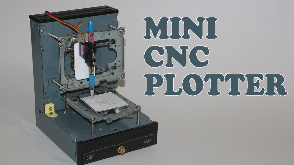
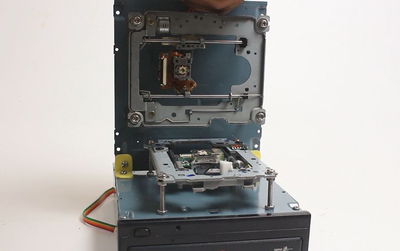
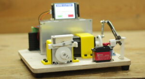
CNC plotter machine is basically a 2.5 axis CNC machine, it have two stepper motor on both X & Y axis and a servo motor at Z axis.
A pen is connected on Y-axis and Z-axis is used to make pun up & down.
As name suggest plotter machine obvious draw or plotting a drawing as per given instruction.
To give instruction to machine what to draw a special type of code called G-code is required.
Image will be converted to G-code with the help of special type of software.
afterwards this G-code sends to controller and controller commands motors how to move.
As result machine will draw image on paper.
Now lets we will see how to build such machine. starting with material list
MATERIAL LIST
| Sr No. | ITEM | QTY |
| 1 | Scrap DVD Drive | 2 |
| 2 | Arduino UNO | 1 |
| 3 | L293D MOTOR SHIELD | 1 |
| 4 | MINI SERVO MOTOR | 1 |
| 5 | 5V 1Amps POWER ADAPTER | 1 |
| 6 | SOME WIRES FOR MOTOR CONNECTION | —- |
| 7 | NUT AND BOLTS AS REQUIRED | —- |
SOFTWARE LIST
Please download the software from above link, and install them on your PC.
CODE AND LIBRARY
| 1 | CNC CODE FOR ARDUINO |
| 2 | GCTRL PROCESSING CODE |
| 3 | AFMOTOR LIBRARY FOR ARDUINO |
| 4 | Makerboat Gcode Inkscape extension |
“CNC CODE FOR ARDUINO” needs to be upload on arduino.
“GCTRL” needs to be open in processing software.
“AFMOTOR” library need to add in arduino IDE
how to do all this ? we’ll see further.
MACHINE ASSEMBLY
Step 1.
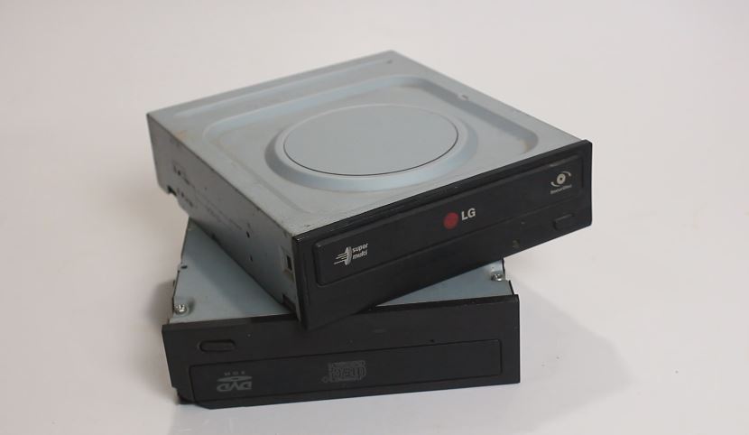
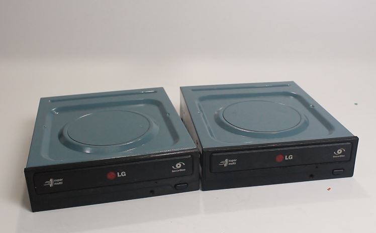
To make Arduino based mini CNC plotter machine obviously we need two scrap DVD drive.
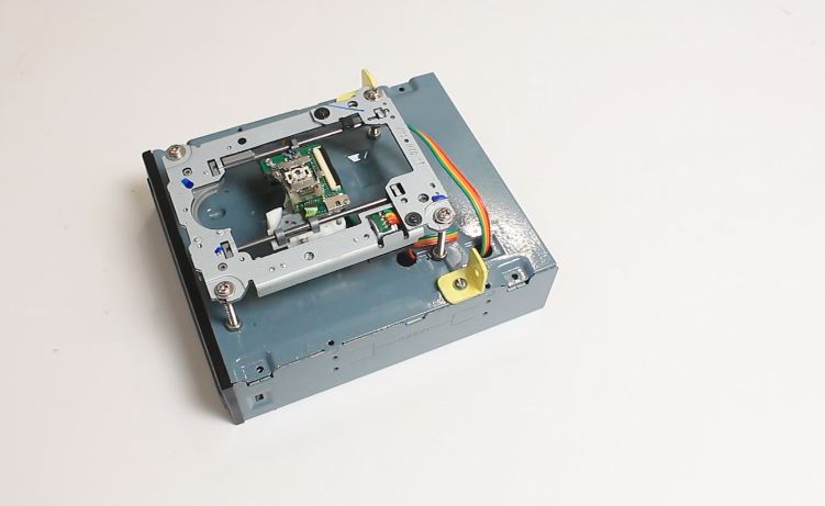
I purchased this drive from local computer repairing shop in less then 1$ .
we’ll going to use its stepper motor along with sliding mechanism
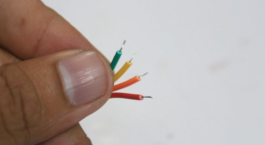
here note that not all DVD drives have stepper motor in it. if the motor have 4 wires it means it is a stepper motor.
if you not found any 4 wire motor in DVD drive then it is use less.
Step 2.
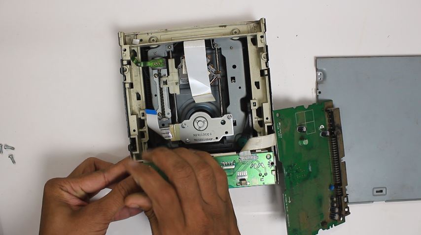
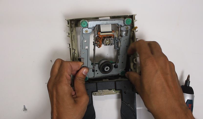
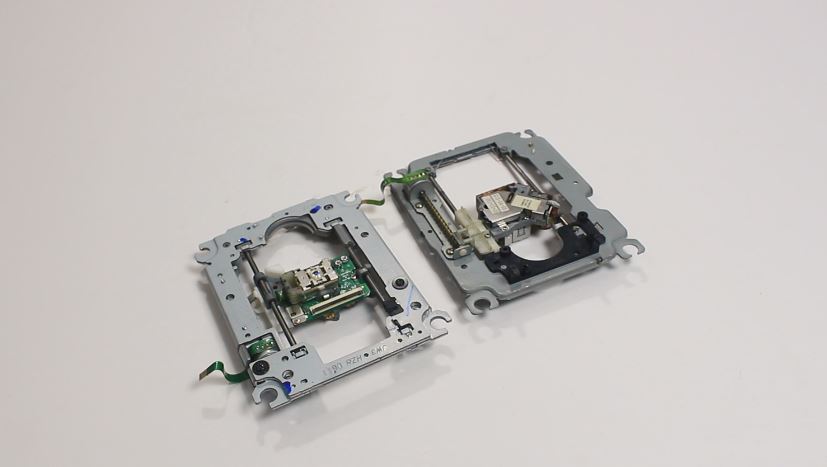
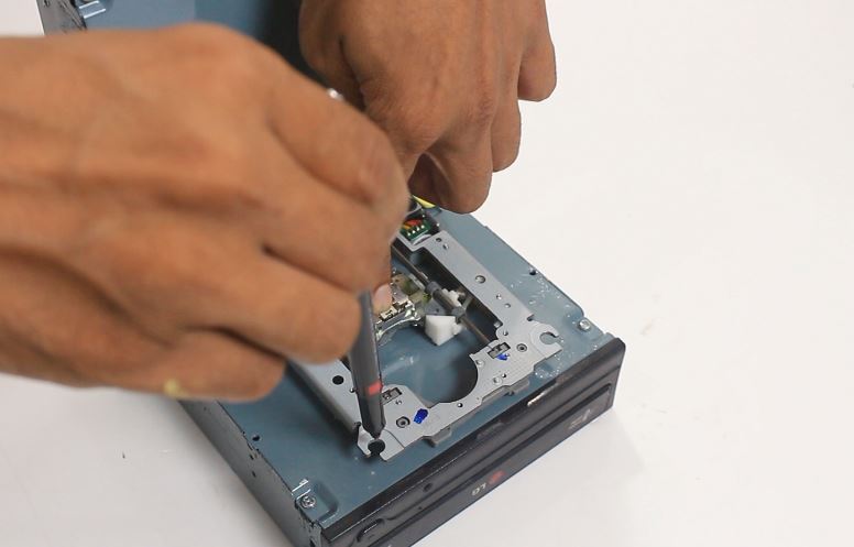
I quickly unscrew the DVD drive case with the help of screw driver and by applying some force I take out the stepper motor mechanism from the DVD drive case.
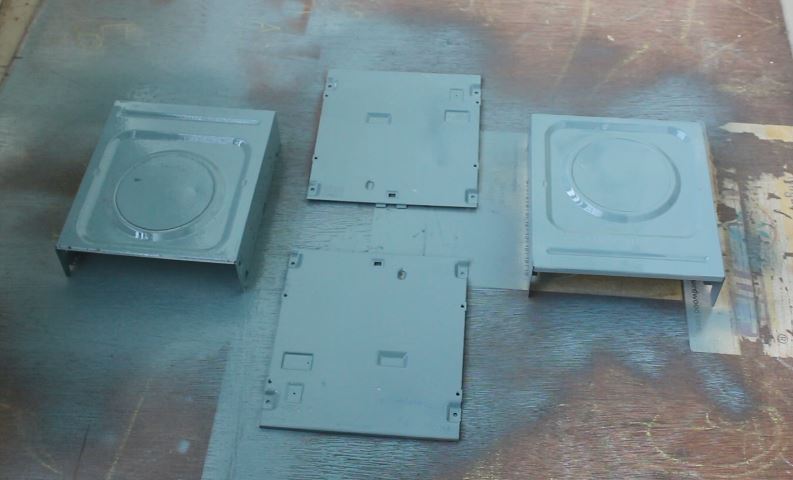
In this way I have two stepper driver mechanism and two empty case of DVD drive.
Step 3.

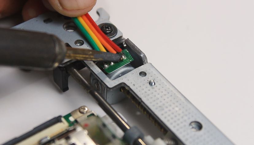
After taking out stepper motor mechanism I cut the default motor connector strip with the help of scissor.
then I bring some DuPont 4 wire of around 40 cm and cut it into 2 pieces one for each stepper motor connection.
Then I strip the wire carefully without damaging the copper strain of wire.
and solder it to the expose terminals of stepper motor.
Step 4.
Step 5.
Here I have paint the the empty case of DVD drive using gray shade spray paint, this step is not compulsory its ok if you don’t want to paint them.
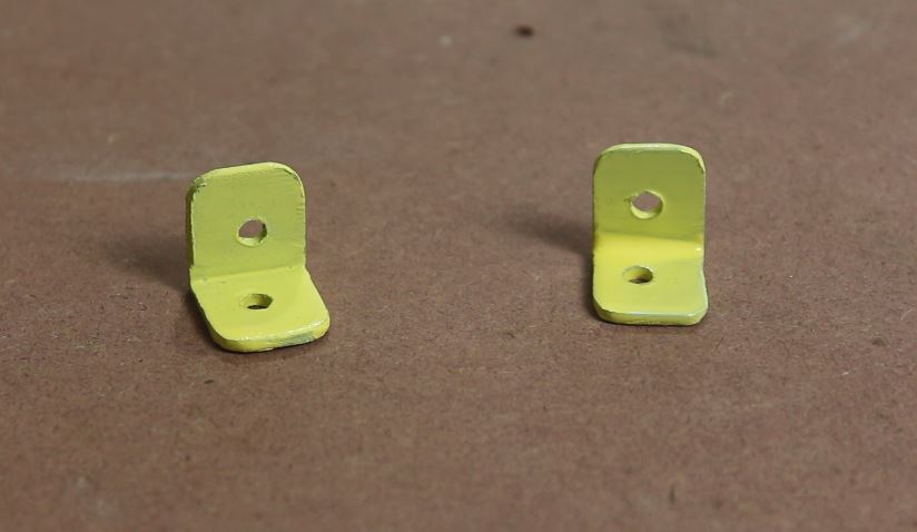
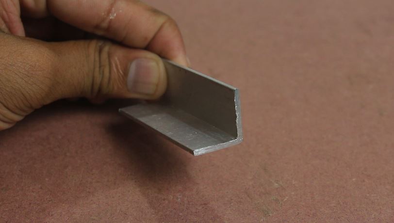

Then I used a piece of 20 x 20 mm aluminium angle to make holder for X-axis and Y-axis .
I drill the 5mm hole on the aluminium piece and cut it into two piece of clamp, further I use this clamp to fix the both axis with the help of M5X10 nut and bolt.
Step 6.
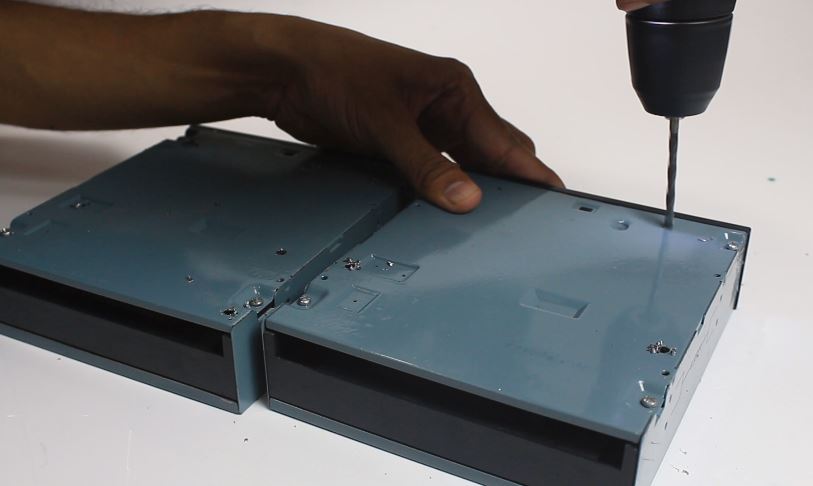
Now I am marking for hole on DVD drive case to make arrangement for mounting for both stepper motor mechanism.
I carefully drill the hole of 5mm with the help of drill machine.
Step 7.
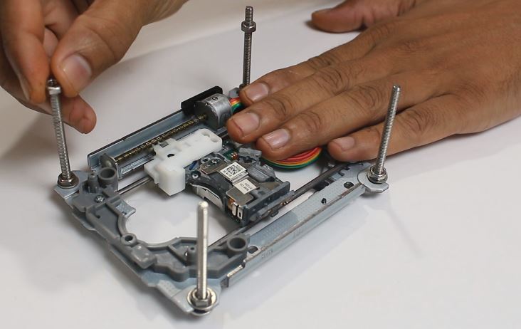
After drilling the hole in DVD drive case I fix the four M4 X 60 nut bolts at the four corner of stepper motor mechanism.
Now I placed the stepper motor mechanism to its place and secure all four bolts with M4 nuts.
Step 8.
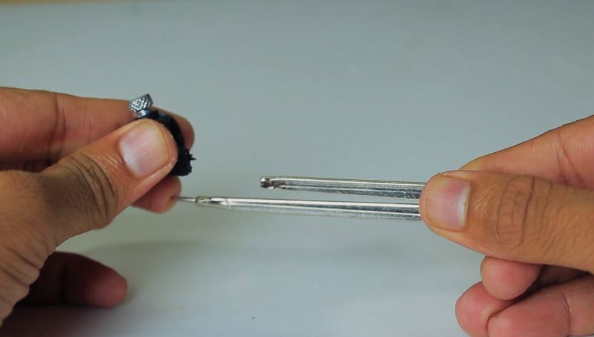


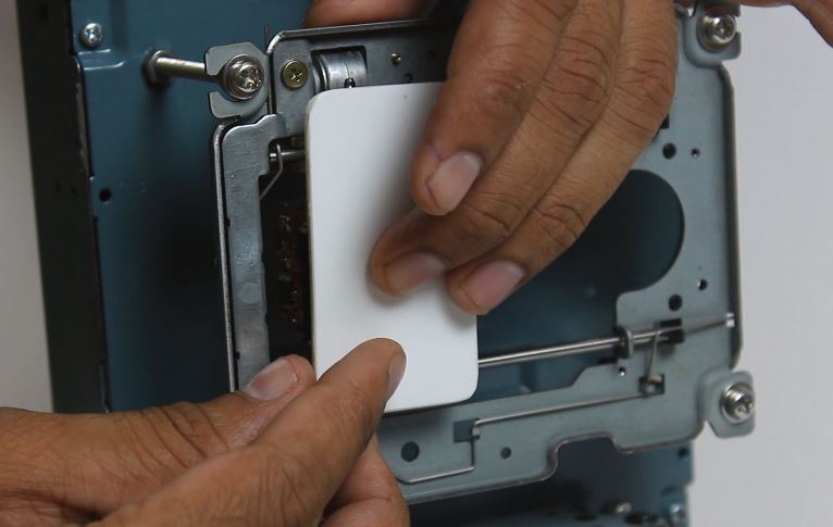
This the is most important step in making mini Arduino CNC plotter machine here we are making pen up and down mechanism.
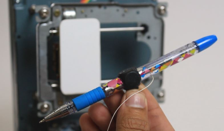
First I take a compass and carefully remove its pen holder part.
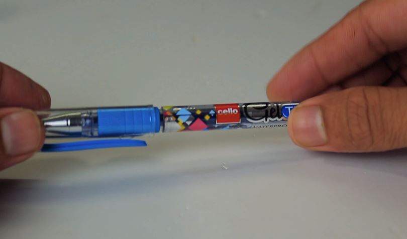
then I used a simple pen with top and bottom openable.
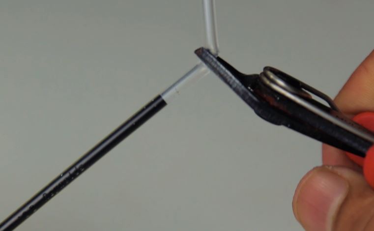
first take out the refill of pen and cut about 2 cm part from the top of the refill.
now I place a spring at the top of the refill which I have salvage from other trigger type pen.
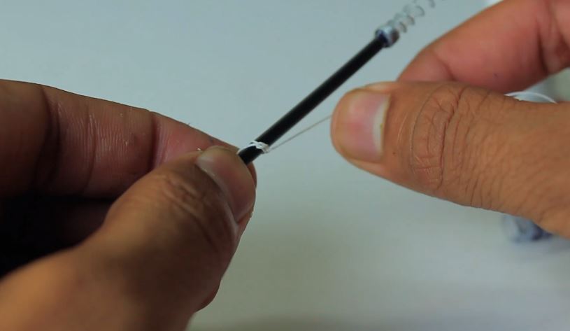
then I used a strong thread and tied it to the center of the refill and secure it with super glue on to its place.
now I make a small hole just above from the center of pen body.
Now I carefully place the refill inside the pen and passed thread outside from the hole.
In this way I made my pen up down mechanism, when I pull the thread pen refill push upward and when I release the thread refill went down.
and due to the spring attached at top of the refill pen tip will maintain a good friction with paper..
Pen is now placed in pen holder and glue it with super glue on the X-axis
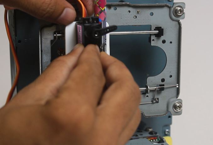
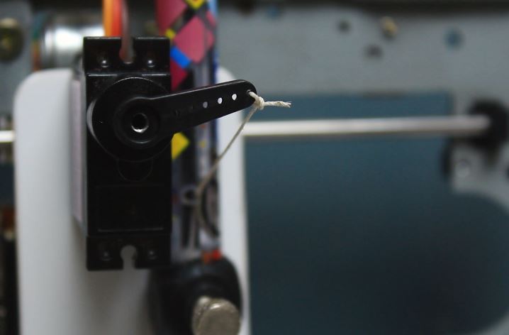
I attached a mini servo at X-axis and tie the thread with the knob of mini servo motor.
Step 9.
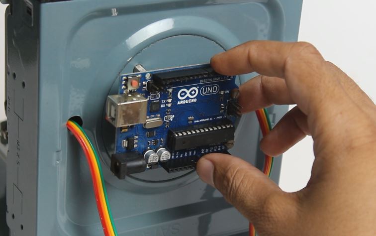

I drill four hole on the back side of machine and screw four 15mm spacer to mount arduino UNO onto it.
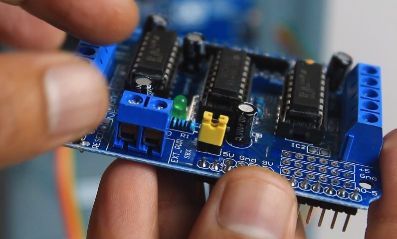
L293D motor shield is mounted on Arduino UNO.
In this way assembly of Arduino CNC plotter machine is competed now we will see the wiring
WIRING
We are using Arduino UNO as a brain of CNC machine, as we know there is stepper motors used in CNC machine.
Stepper motors are not easy to control so here we are using a L293D motor shield to control our stepper motors and one servo motor is used for pen up down movement.
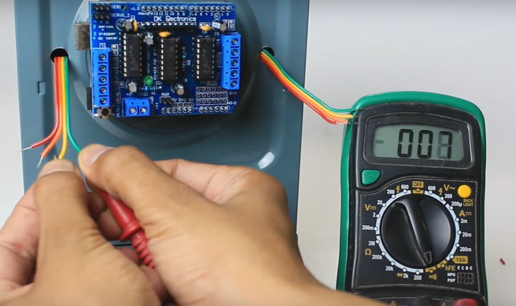
Before start wiring first we nee to the know the correct wire of stepper motor.
Our stepper motor have 4 wire and stepper motor have two coils means the a set of two wire is form one coil.
so we need to find out which two wires are from one coil, so here I am using multimeter keeping multimeter on continuity test.
I connect the mutimeter prob to the wires one by one, if I get continuity( few ohms) between any two wires means that both wires belong to single coil and rest two are from other coil.

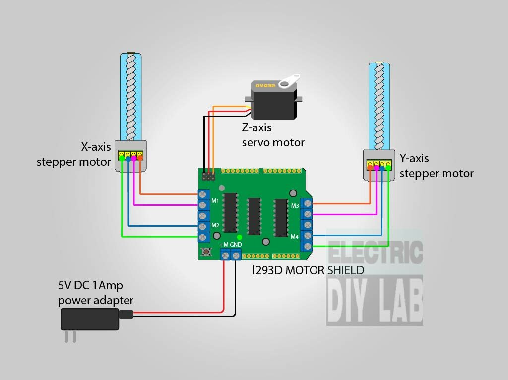
Don’t forget to remove that yellow jumper, and connect the stepper motor wires as shown in drawing above.
and also connect the servo motor at servo 1 terminal of L293D Motor shield.
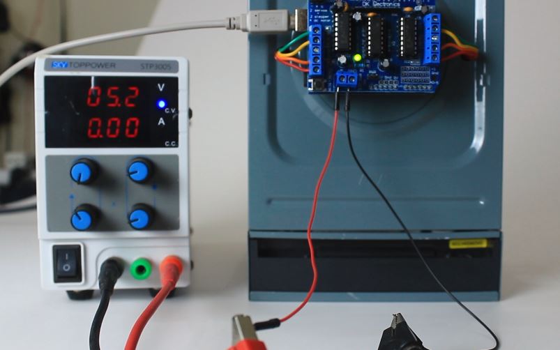
You need a power adapter to feed power to the machine, you can use 5VDC 1amps power adapter.
In this way wiring is completed now we can move towards arduino code uploading process.
ARDUINO CODE
Hope you have downloaded the arduino code and library from above in post if not, don’t worry you can download it from the below links.
Arduino code
AFMotor Library
First of all we need to install AFMotor library in arduino IDE if you dont know how to add library just google it.
Now simple upload the code without changing anything
Here I am explaining some important part of code which may useful for you
Followings are the servo up down values Increase or decrease if required. if servo works in opposite direction switch the value of punZUp & penZDown values.
// Servo position for Up and Down
const int penZUp = 120;
const int penZDown = 50;
Below are the value to change the speed of cnc plotter machine youcan change the the value of StepDelay from 0 to 2,
0 is for maximum speed and 2 is for minimum speed, ideally keep it at 1.
float StepInc = 1;
int StepDelay = 1;
int LineDelay =0;
int penDelay = 50;
If your plotting area is bigger then you can change the Xmax & Ymax value from here.
float Xmin = 0;
float Xmax = 40;
float Ymin = 0;
float Ymax = 40;
float Zmin = 0;
float Zmax = 1;
Complete Code for arduino Mini CNC plotter mahcine
#include <Servo.h>
#include <AFMotor.h>

#define LINE_BUFFER_LENGTH 512

char STEP = MICROSTEP ;

// Servo position for Up and Down
const int penZUp = 120;
const int penZDown = 50;

// Servo on PWM pin 10
const int penServoPin =10 ;

// Should be right for DVD steppers, but is not too important here
const int stepsPerRevolution = 48;

// create servo object to control a servo
Servo penServo;

// Initialize steppers for X- and Y-axis using this Arduino pins for the L293D H-bridge
AF_Stepper myStepperY(stepsPerRevolution,1);
AF_Stepper myStepperX(stepsPerRevolution,2);

/* Structures, global variables    */
struct point {
  float x;
  float y;
  float z;
};

// Current position of plothead
struct point actuatorPos;

//  Drawing settings, should be OK
float StepInc = 1;
int StepDelay = 1;
int LineDelay =0;
int penDelay = 50;

// Motor steps to go 1 millimeter.
// Use test sketch to go 100 steps. Measure the length of line.
// Calculate steps per mm. Enter here.
float StepsPerMillimeterX = 100.0;
float StepsPerMillimeterY = 100.0;

// Drawing robot limits, in mm
// OK to start with. Could go up to 50 mm if calibrated well.
float Xmin = 0;
float Xmax = 40;
float Ymin = 0;
float Ymax = 40;
float Zmin = 0;
float Zmax = 1;

float Xpos = Xmin;
float Ypos = Ymin;
float Zpos = Zmax;

// Set to true to get debug output.
boolean verbose = false;

//  Needs to interpret
//  G1 for moving
//  G4 P300 (wait 150ms)
//  M300 S30 (pen down)
//  M300 S50 (pen up)
//  Discard anything with a (
//  Discard any other command!

/**********************
 * void setup() - Initialisations
 ***********************/
void setup() {
  //  Setup

  Serial.begin( 9600 );

  penServo.attach(penServoPin);
  penServo.write(penZUp);
  delay(100);

  // Decrease if necessary
  myStepperX.setSpeed(600);

  myStepperY.setSpeed(600);


  //  Set & move to initial default position
  // TBD

  //  Notifications!!!
  Serial.println("Mini CNC Plotter alive and kicking!");
  Serial.print("X range is from ");
  Serial.print(Xmin);
  Serial.print(" to ");
  Serial.print(Xmax);
  Serial.println(" mm.");
  Serial.print("Y range is from ");
  Serial.print(Ymin);
  Serial.print(" to ");
  Serial.print(Ymax);
  Serial.println(" mm.");
}

/**********************
 * void loop() - Main loop
 ***********************/
void loop()
{

  delay(100);
  char line[ LINE_BUFFER_LENGTH ];
  char c;
  int lineIndex;
  bool lineIsComment, lineSemiColon;

  lineIndex = 0;
  lineSemiColon = false;
  lineIsComment = false;

  while (1) {

    // Serial reception - Mostly from Grbl, added semicolon support
    while ( Serial.available()>0 ) {
      c = Serial.read();
      if (( c == '\n') || (c == '\r') ) {             // End of line reached
        if ( lineIndex > 0 ) {                        // Line is complete. Then execute!
          line[ lineIndex ] = '\0';                   // Terminate string
          if (verbose) {
            Serial.print( "Received : ");
            Serial.println( line );
          }
          processIncomingLine( line, lineIndex );
          lineIndex = 0;
        }
        else {
          // Empty or comment line. Skip block.
        }
        lineIsComment = false;
        lineSemiColon = false;
        Serial.println("ok");
      }
      else {
        if ( (lineIsComment) || (lineSemiColon) ) {   // Throw away all comment characters
          if ( c == ')' )  lineIsComment = false;     // End of comment. Resume line.
        }
        else {
          if ( c <= ' ' ) {                           // Throw away whitepace and control characters
          }
          else if ( c == '/' ) {                    // Block delete not supported. Ignore character.
          }
          else if ( c == '(' ) {                    // Enable comments flag and ignore all characters until ')' or EOL.
            lineIsComment = true;
          }
          else if ( c == ';' ) {
            lineSemiColon = true;
          }
          else if ( lineIndex >= LINE_BUFFER_LENGTH-1 ) {
            Serial.println( "ERROR - lineBuffer overflow" );
            lineIsComment = false;
            lineSemiColon = false;
          }
          else if ( c >= 'a' && c <= 'z' ) {        // Upcase lowercase
            line[ lineIndex++ ] = c-'a'+'A';
          }
          else {
            line[ lineIndex++ ] = c;
          }
        }
      }
    }
  }
}

void processIncomingLine( char* line, int charNB ) {
  int currentIndex = 0;
  char buffer[ 64 ];                                 // Hope that 64 is enough for 1 parameter
  struct point newPos;

  newPos.x = 0.0;
  newPos.y = 0.0;

  //  Needs to interpret
  //  G1 for moving
  //  G4 P300 (wait 150ms)
  //  G1 X60 Y30
  //  G1 X30 Y50
  //  M300 S30 (pen down)
  //  M300 S50 (pen up)
  //  Discard anything with a (
  //  Discard any other command!

  while( currentIndex < charNB ) {
    switch ( line[ currentIndex++ ] ) {              // Select command, if any
    case 'U':
      penUp();
      break;
    case 'D':
      penDown();
      break;
    case 'G':
      buffer[0] = line[ currentIndex++ ];          // /!\ Dirty - Only works with 2 digit commands
      //      buffer[1] = line[ currentIndex++ ];
      //      buffer[2] = '\0';
      buffer[1] = '\0';

      switch ( atoi( buffer ) ){                   // Select G command
      case 0:                                   // G00 & G01 - Movement or fast movement. Same here
      case 1:
        // /!\ Dirty - Suppose that X is before Y
        char* indexX = strchr( line+currentIndex, 'X' );  // Get X/Y position in the string (if any)
        char* indexY = strchr( line+currentIndex, 'Y' );
        if ( indexY <= 0 ) {
          newPos.x = atof( indexX + 1);
          newPos.y = actuatorPos.y;
        }
        else if ( indexX <= 0 ) {
          newPos.y = atof( indexY + 1);
          newPos.x = actuatorPos.x;
        }
        else {
          newPos.y = atof( indexY + 1);
          indexY = '\0';
          newPos.x = atof( indexX + 1);
        }
        drawLine(newPos.x, newPos.y );
        //        Serial.println("ok");
        actuatorPos.x = newPos.x;
        actuatorPos.y = newPos.y;
        break;
      }
      break;
    case 'M':
      buffer[0] = line[ currentIndex++ ];        // /!\ Dirty - Only works with 3 digit commands
      buffer[1] = line[ currentIndex++ ];
      buffer[2] = line[ currentIndex++ ];
      buffer[3] = '\0';
      switch ( atoi( buffer ) ){
      case 300:
        {
          char* indexS = strchr( line+currentIndex, 'S' );
          float Spos = atof( indexS + 1);
          //         Serial.println("ok");
          if (Spos == 30) {
            penDown();
          }
          if (Spos == 50) {
            penUp();
          }
          break;
        }
      case 114:                                // M114 - Repport position
        Serial.print( "Absolute position : X = " );
        Serial.print( actuatorPos.x );
        Serial.print( "  -  Y = " );
        Serial.println( actuatorPos.y );
        break;
      default:
        Serial.print( "Command not recognized : M");
        Serial.println( buffer );
      }
    }
  }


}


/*********************************
 * Draw a line from (x0;y0) to (x1;y1).
 * int (x1;y1) : Starting coordinates
 * int (x2;y2) : Ending coordinates
 **********************************/
void drawLine(float x1, float y1) {

  if (verbose)
  {
    Serial.print("fx1, fy1: ");
    Serial.print(x1);
    Serial.print(",");
    Serial.print(y1);
    Serial.println("");
  }

  //  Bring instructions within limits
  if (x1 >= Xmax) {
    x1 = Xmax;
  }
  if (x1 <= Xmin) {
    x1 = Xmin;
  }
  if (y1 >= Ymax) {
    y1 = Ymax;
  }
  if (y1 <= Ymin) {
    y1 = Ymin;
  }

  if (verbose)
  {
    Serial.print("Xpos, Ypos: ");
    Serial.print(Xpos);
    Serial.print(",");
    Serial.print(Ypos);
    Serial.println("");
  }

  if (verbose)
  {
    Serial.print("x1, y1: ");
    Serial.print(x1);
    Serial.print(",");
    Serial.print(y1);
    Serial.println("");
  }

  //  Convert coordinates to steps
  x1 = (int)(x1*StepsPerMillimeterX);
  y1 = (int)(y1*StepsPerMillimeterY);
  float x0 = Xpos;
  float y0 = Ypos;

  //  Let's find out the change for the coordinates
  long dx = abs(x1-x0);
  long dy = abs(y1-y0);
  int sx = x0<x1 ? StepInc : -StepInc;
  int sy = y0<y1 ? StepInc : -StepInc;

  long i;
  long over = 0;

  if (dx > dy) {
    for (i=0; i<dx; ++i) {
      myStepperX.onestep(sx,STEP);
      over+=dy;
      if (over>=dx) {
        over-=dx;
        myStepperY.onestep(sy,STEP);
      }
    delay(StepDelay);
    }
  }
  else {
    for (i=0; i<dy; ++i) {
      myStepperY.onestep(sy,STEP);
      over+=dx;
      if (over>=dy) {
        over-=dy;
        myStepperX.onestep(sx,STEP);
      }
      delay(StepDelay);
    }
  }

  if (verbose)
  {
    Serial.print("dx, dy:");
    Serial.print(dx);
    Serial.print(",");
    Serial.print(dy);
    Serial.println("");
  }

  if (verbose)
  {
    Serial.print("Going to (");
    Serial.print(x0);
    Serial.print(",");
    Serial.print(y0);
    Serial.println(")");
  }

  //  Delay before any next lines are submitted
  delay(LineDelay);
  //  Update the positions
  Xpos = x1;
  Ypos = y1;
}

//  Raises pen
void penUp() {
  penServo.write(penZUp);
  delay(penDelay);
  Zpos=Zmax;
  digitalWrite(15, LOW);
    digitalWrite(16, HIGH);
  if (verbose) {
    Serial.println("Pen up!");

  }
}
//  Lowers pen
void penDown() {
  penServo.write(penZDown);
  delay(penDelay);
  Zpos=Zmin;
  digitalWrite(15, HIGH);
    digitalWrite(16, LOW);
  if (verbose) {
    Serial.println("Pen down.");


  }
}
As of now code is uploded its time to generate G-code
G-CODE GENERATION
To draw something with CNC plotter machine we obviously needs G-code,
G-code is the language of CNC machine.
In this project we are using Inkscape software and makerboat G-code library to generate G-code of image.
First off all download the Inkscape 0.48.5 version and download the makerboat gcode extension.
Install the Inkscape software and add the extension as per below.
To understand the complete process of G-code generation I request you to watch the below video.
If you further have any issue you are welcome in comment section.
Only you have to note that you have to download inkscape 0.48.5 version only
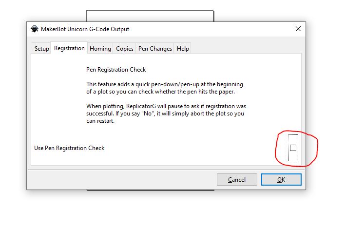
NOTE:- if you arduino get disconnected or reset when machine is just about to start un-check to below option while exporting G-code
NOTE:- If your machine is plotting only some half part of drawing so you can use this template of inkscape download this template and open it in inkscape and set you design in dotted frame

GCTRL
At this point our machine is ready to plot anything just waiting for command,
We also have generated G-code but how to send this G-code to machine?
for this job We are using GCTRL a G-code sender GUI for processing.
We are streaming G-code to machine with the help of processing and GCTRL
Hope you have downloaded GCTRL from above if not download it from here
Simple open the GCTRL.pde by double clicking on it
Now click on play button visible on the top right corner of processing window,
this type of window will appears
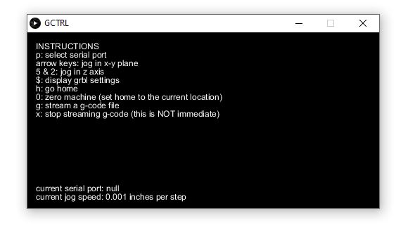
All the details regarding how to use this GUI is clearly written there itself.
By pressing the key “p” you can select the COM port from the drop down list.
after selecting the port you can jog X & Y axis with the help of arrow key.
use numerical key “5” & “2” to jog pen up and down.
To send G-code to arduino press key “g” and select the G-code file from the brows window as soon you select the fill and hit enter machine start to plot the drawing.
In this way the process of making Arduio based Mini CNC plotter machine is competed hope I have covered major points if you need to ask any question just simply comment in the comment section below. I’ll try my best to answer you.

One more remark to this awesome project and documentation:
when I did my first drawings I noticed that it only drew 1/4 of the picture. For example: if I wanted to draw a circle I would only get a 90 degree “pie”.
Then I noticed that in Sandeep’s video the “home” of the pen is in the upper left, but in my machine the pen would return to the middle of the paper when done.
I got it to work by making the following change, starting in line 47:
// Drawing robot limits, in mm
// OK to start with. Could go up to 50 mm if calibrated well.
float Xmin = -20;
float Xmax = 20;
float Ymin = -20;
float Ymax = 20;
float Zmin = 0;
float Zmax = 1;
after that i got the whole drawing. My best guess is that there are differences in the AFMotor libraries.
Hi sandeep thanks for such detailed overview! appreciate it!
And can you help me with one thing?
My Y axis motor is not responding when I push a G-code file but the X axis and the servo is doing fine!
I hv double checked the connection and both the steppers are properly connected ( I did a basic increment decrement test separately)
Did this issue arise on your end?
Thanks in advance! 🙂
is it completely dead while streaming G-code ? or it vibrate without any motion..
What is the size of the plate the paper sits on
50 mm x 50 mm
how are we suppose to open the GCTRL.pde file on windows ? double clicking doesn’t do a thing
you need a software called processing to open .pde files
What if i don’t have a power adaptor?
you can use battery
Hello sir im rahul from bhandup im doing this project for my iti clg tech fest…bt im facing the servo motor issue…that the servo motor is not working properly
Hi, I’m currently running an exact project with arduino uno, cnc shield v3, 2 stepper motor and 1 servo. The power adapter im using is 12volts however, the servo doesn’t work. I test the servo but it works just fine like usual. Is it because it doesn’t have enough voltage to supply?
Hi, thank you for the helpful instructions! I have one issue: the pen does not move up when sketching (however, it moves up and down just fine when testing the gctrl code, before streaming the gcode file). What can I do to fix this?
bro i am getting this message in Processing software
M18 (drives off)
Command not recognized : M18
How to solve this problem…? Thanks!
First of all to Sandeep, FANTASTIC detailed instructions! Thank you so much!
To the question about “M18”.
“M18” simply means pretty much “end of file”, so technically it’s not an error.
Sandeep’s code doesn’t parse for “M18”.
Here is what I did:
I changed the code, starting at line 259 like this, this gets rid of the error message AND also turns the drives off, so that they don’t make an annoying buzzing sound.
default:
if ((buffer[0] == ‘1’) && (buffer [1] == ‘8’)){ // M18 = drives off
Serial.println( “M18: we’re done, turn drives off”);
myStepperX.release();
myStepperY.release();
}
else {
Serial.print( “Command not recognized : M”);
Serial.println( buffer );
}
this is the best solution christopher thumbs up..
Sandeep sir without using arduino IDE and processing IDE
Why am say this coz every Gcodes i upload on arduino IDE are giving errors
Can we make GCodes
Can we use Inkscape and CAmotics
On arduino UNO R3 and motor shield l293d???
Sir please reply for me
hola alguien me puede decir o ayudar con esto ya que quiero empezar hacer mi propia cnc y es que confundo con el programa.. que está en el lace eso lo debo copiar y pasarlo ar arduino y al al l293d toda es información que esta el la pajina….
Sir will you show us in YouTube
How we should download the AFmotor library in arduino IDE
I download link in notepad I seen codes
But problem is that codes are clumsy
Pls help us
There are many videos on youtube that may help you in this..
Thanks for replying but I got solution there before yesterday i just copied all AFmotor library files in arduino IDE
The codes set itself
Do you remember me sandeep sir
We meet 3years back in what’s app too
Me from visakhapatnam
I hope you remember me
bro i have a following error
M18 (drives off)
Command not recognized : M18
how to solve it?
Hello, I also have this error. please help
Can I control CNC with Android smartphone
Hello, the inkscape software has no 64 bit version
It doesn’t need at all 32 bit works well on 64 bit system..
Okay..I have done that. However I’m getting the Command not recognize M18 error. Please help
Bro in Processing Software 3.5.3 I am getting this error…:
The method showInputDialog(Component, Object, String, int, Icon, Object[], Object) in the type JOptionPane is not applicable for the arguments (ProcessingFileCNC, String, String, int, null, String[], int)
I would be really thankful if you can help me out… Thanks in advance!
(Reminder: ProcessingFileCNC is the same .pde file… I just renamed it)
Your line number 31 in processing should be like this “String result = (String) JOptionPane.showInputDialog(frame,” ignore double quote.
it looks you have not downloaded the GCTRL from the given links, please read the complete post 2, 3 times carefully and download the file which I have mentioned if you followed each and every step as suggested you will not face such issues…
OK… Thanks a lot BRO!
Great work indeed!
Bro, does it need live interfacing with computer or i can do it on my home made arduino by programming the Atmega328p?
Please help!
It is advisable to use ready made arduino uno…
Can you please tell me how many watts soldering iron you have used for soldering stepper motor terminals?
Sir can I use 9v volts battery on L293D motor shield
Yes you can use
https://www.youtube.com/watch?v=kcz1ygh20c0&list=LLPkRWBsaNd99p4VOaBwyRMA
about this project why my command in universal gcode sender dont function,can u help me?
Very good, I had a problem with the Mini CNC.
Send the execution of the drawing or figure and run more than it should, so it draws things halfway out of the given parameters.
Thank you !
Sir how to mount it ?please tell.
Sir can I use Arduino mega instead of Arduino uno ?
please tell me if there is a difference in its constructing method.
yes you can
Excellent work
Can u tell me how much did this DC Power Supply Machine (or whatever is its actual name) cost?
What is its actual name?
And what is its starting price in market?
https://www.aliexpress.com/item/32914365640.html
OK Thanks… And which soldering iron is used? Mine is having trouble soldering the wires on stepper motor… Is that because of high watts?
I am trying to make a CNC Plotter (you can also call it Writing Machine)… In a tutorial on intructables.com they have used
Arduino UNO
2* Stepper Motors from DVD Drives
Mini Servo Motor
Jumper Wires
2* L293D ICs (Remember: This is not L293D Motor Driver Shield…It is just a small IC)
Breadboard
Parts mentioned in first four are found in almost every tutorial on YouTube as well, but, in this tutorial they have used two L293D ICs instead of the L293D Motor Driver Shield and used a bread board for connecting all the parts…
They also cut the USB wire and attached another wire to increase amperes but I did not do so…This is how they did it… Image Link: https://cdn.instructables.com/ORIG/FVF/FAZG/IHQMAMCP/FVFFAZGIHQMAMCP.jpg
The issue is that…
… One of the two stepper motors is vibrating very much but there is no movement…
….I told someone about this issue and they recommended me to add an external power supply (not to connect in the DC power jack of Arduino UNO)… I would like to know according to the circuit diagram of my project where should I connect the power supply?
….. I have 2* 3.7V 18650 cells which means a total of 7.4V… Would that be enough?
…. I also have a 9V 2A Adapter for Modem… Should I use this?
….And most important… Is power supply REALLY the solution for this vibration of stepper Motor?
Link:https://www.instructables.com/id/Arduino-Mini-CNC-Plotter-Machine-from-dvd-drives/
I recommend you first you check stepper motor individual if motors are ok then you can increase power upto 9 v if motor does not get very hot, if you can touch motor for 5 seconds it’s means motors are not that hot
ok…. Thanks a lot… I will tell u after doing as u mentioned…
May I know your pc’ configuration thanks
It’s win10 I5 8gb ram
Oh that’s good… Can u plz tell which generation of i5… Thanks…. Graphics card?(if any)?
Thanks !
7th gen Intel hd 620
OK Thanks a lot!
Can I control CNC with Android smartphone?
Dude i am unable to open “cnc code.ino” whenever i try to open it using my arduino IDE software i keep getting “this sketch could not be opened” i dont know what to do pls fix it or give us the that we can copy & paste. Thanking You
Bro code is perfectly opening in arduino Ide you can do one thing after downloading arduino code right click on it and open in any text editor (notepad) and copy all content and past in arduino ide
I also updated code on website you can download from there also.
You can’t open it
Just go to the arduino app and try to open it
use arduino web editor
Very Nice Effort!
Can I know how to do this without L293D Motor Driver Shield?
I do have two small L293D ICs
Thanks in advance
you can follow this wiring drawing rest all is same
https://cdn.instructables.com/FM3/K07F/JBGU8SP9/FM3K07FJBGU8SP9.LARGE.jpg?auto=webp&width=1024&height=1024&fit=bounds
Thanks alot for helping me out… Actually I am having Arduino UNO while in this video the board used is the Arduino Nano I think…. Would like to know ur advice regarding how to do with Arduino UNO…. Further I also made a new comment describing my complete problem…. Plz see that also…. Thanks again..
Please check once again in this project Arduino uno is used no nano
Oh sorry… I meant to say that picture you gave link of…
Ok don’t worry it doesn’t matter just connect wires on the same pin of uno
Ok… Will tell u after doing as u mentioned…
Sure