
LDR Darkness sensor circuit
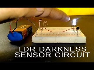
In this article we will see how can we build a darkness sensor by using LDR sensor. This sensor detect light falling on it and change it resistance accordingly.
This change in resistance of LDR detect by a circuit. Which turn led ON When light is not falling on LDR and turn LED OFF when light falling on LDR.
By using such characteristic of LDR we can build a LDR Darkness sensor circuit which turn ON light in darkness and turn OFF light when there is sufficient light. Also we can build reveres of it also if required.
How it works
LDR stands for light dependent resistor, as name suggest it is a type of resistor whose resistance is depends on the amount of light falling on it.
LDR is made up of high resistance semiconductor.
When light photons fall on LDR this photons are absorbed by the semiconductor this gives enough energy to the bound electron to jump to the conductive band.
as a result free electron as available in LDR this makes it more conductive and drop in resistance of LDR.
In dark its resistance is high as several mega ohm, and in light its down to few ohms.
This change in resistance of LDR will detect by a circuit and it will turn on LED accordingly, we will see such type of circuit in below examples.
VIDEO
Here is the video of project in action, you can watch the video and for more details continue to read the post.
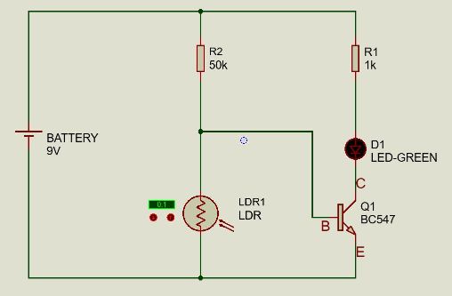
LDR Circuit to turn on LED in dark
Component used
9V battery
LDR sensor
50K, 1K Ohm resistor
BC547 Transistor
So when sufficient light falling on LDR the resistance of LDR in very low, as a result all current is flowing from resistor R2 AND LDR so LED D1 is not glowing,
When there is dark and no light is falling on LDR, so the LDR resistance became very high so current will flow ro the base of transistor Q1 BC547, so transistor became turn on, and LED D1 glow.
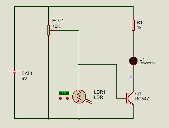
LDR Circuit with adjustable sensitivity using potentiometer
Component used
9V battery
LDR sensor
10K Ohm potentiometer
1K Ohm resistor
BC547 Transistor
In this circuit we can adjust the sensitivity of darkness sensor by using potentiomter,
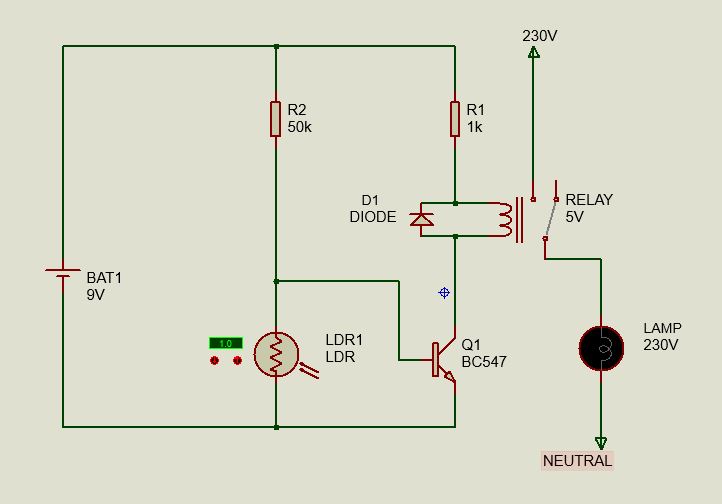
LDR Circuit to glow 230V AC load
Component used
9V battery
5V DC relay
230V AC Lamp
50K, 1K Ohm resistor
1N4007 Diode
BC547 Transistor
50K, 1K Ohm resistor
BC547 Transistor
This Circuit is to operate 230V AC bulb or light on LDR circuit.
This will use in our house, garage, factory, building, street light to turn on lights in dark.
Here also the working principle is same just led is replaced by a DC relay to operate high voltage load,
When light is not falling on LDR the relay will operate and the contact of relay changeover, in this way 230V lamp get connected with 230V supply and start glowing.
A flyback diode 1N4007 is used to save circuit from back EMF generated by relay while de-energizing.


Very very nice, interesting and useful.
Thanks
Is this project related to topic -” Photo Sensor”
Hloo I want to keep the sensor of light for my car to work automatically at night how to prepare it can u explan me