Arduino TIP122 DC motor Control
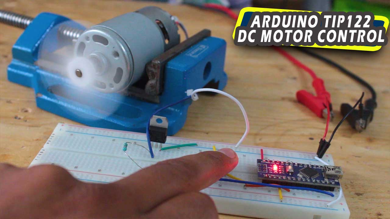
arduino tip122 dc motor control
Hello makers in this post we’ll learn how we can control high rating 755 DC motor with arduino using TIP122
Whenever we need to run a DC motor in our arduino project,
we cannot connect it directly to the digital pins of arduino board because the maximum current rating of digital pin is 40mA.
and DC motor specially in our case 775 12V DC motor draws 0.45Amps if we connect it directly to arduino board you know what happen, it will burn your arduino board.
for such purpouse we are going to use TIP122 NPN Darlington transistor it can handle upto 5A 100V load.
so let see how to control DC motor using arduino and TIP122 NPN transistor
TIP122
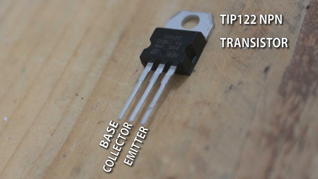
TIP122 is NPN Darlington power transistor it is suitable for low speed switching circuits.
It can handle 5A and 100V load , TIP122 have three terminal legs Base, collector and emitter.
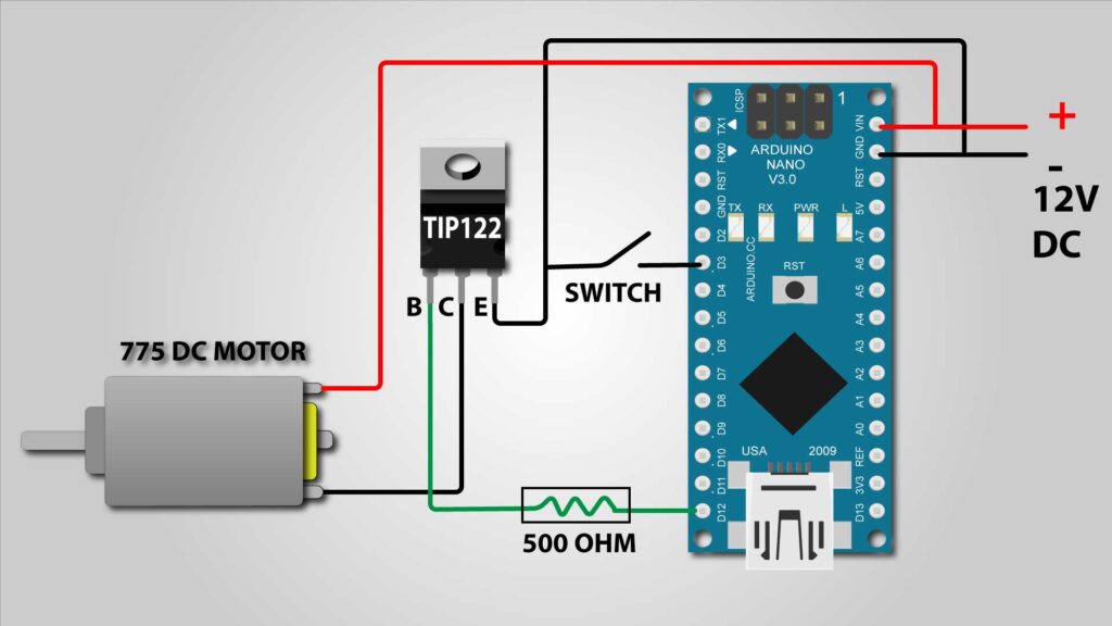
Circuit diagram for Arduino TIP122 DC motor Control
Here we have connected a switch between GND and arduino digital pin 3 and base of TIP122 transistor is connected in series with 500 ohm resistor and digital pin 12 .
to control DC motor when we press the switch, DC motor will turn on and after releasing the switch DC motor will turns off.
Arduino code
At the very binning of the code we declare some variable for pin identification
In void Setup we declare pin modes, pin 12 is output pin and Pin 3 is inputpull pin.
It is good to declare Input pin as input pullup because then we no need to attache any external pullup resistor to the switch.
In normal condition if switch is not pressed the pin 12 is high, when switch is pressed it connected to ground and became low via internal pullup resistor.
So in void loop we used “IF ELSE” function like if switch is pressed then arduino makes output pin high so base pin of transistor gets 5V and turn on the motor through transistor.
else keep the output pin LOW to keep motor turn off.
int motpin = 12;
int button = 3;
void setup() {
  pinMode(motpin, OUTPUT);
  pinMode(button, INPUT_PULLUP);

}

void loop() {
  if (!digitalRead(button)){
    digitalWrite(motpin,HIGH);
  }

  else{
    digitalWrite(motpin,LOW);
  }

}
