Temperature controller circuit using LM358 OP AMP
LM358-TEMPERATURE-CONTROL-CIRCUIT
Hello friends in this video we will learn how we can create a simple circuit to control temperature using LM358 OP AMP IC.
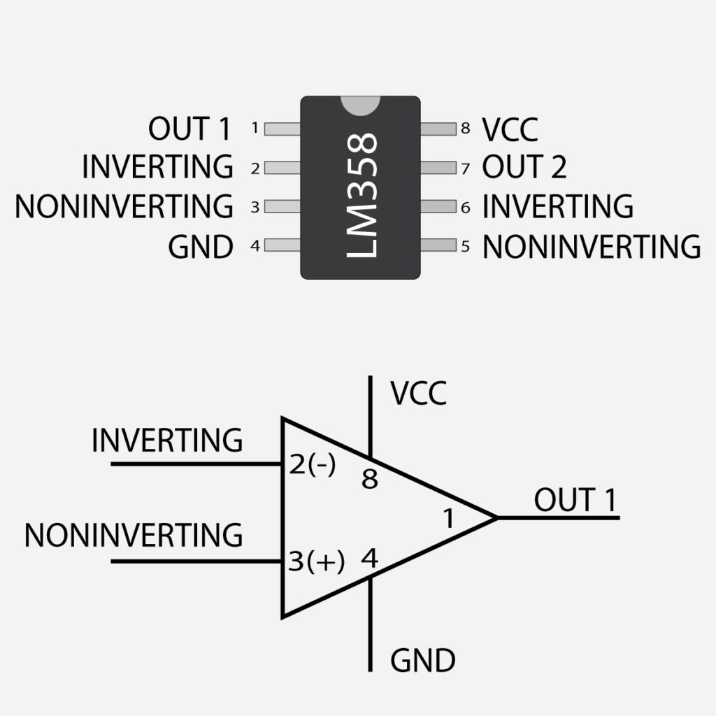
What is LM358 OP AMP ?
LM358 is an operational amplifier and comparator IC. LM358 has 2 set of inverting input and noninverting input and their corresponding outputs.
When the voltage at the noninverting pin is higher compared to the voltage at the noninverting pin the output becomes high.
By using this logic we will develop a circuit to control temperature.
So here we basically understand what LM358 IC is, now let’s move towards our main topic to create a temperature control circuit.
First, we will see the material list going to be used in this project.
Material list
- LM358 OP AMP
- 100K NTC THERMISTOR
- DC RELAY
- 10K POTENTIOMETER
- 10K RESISTOR
- 100K RESISTOR
- S8050 NPN TRANSISTOR
- 1N4007 DIODE
- 230V HEATER
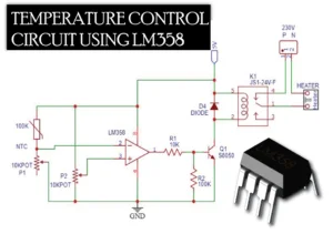
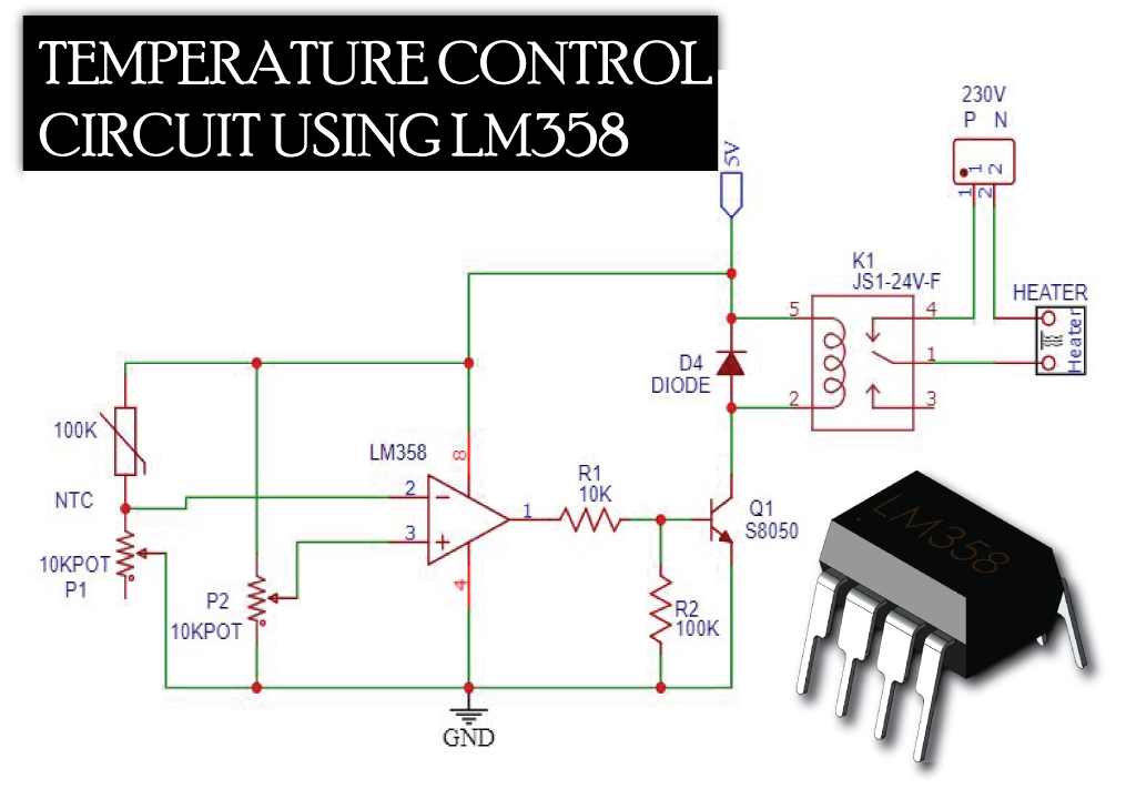
CIRCUIT DIAGRAM
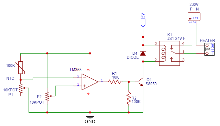
CIRCUIT EXPLANATION
In this circuit 100k NTC thermistor one end is connected to the positive 5V and the other end is connected with 10k pot P1, wiper pin of the potentiometer is connected with inverting pin 2 of LM358.
So when temperature will increase the resistance of NTC will decrease and accordingly voltage at pin 2 increase.
On other hand noninverting pin 3 of LM358 is connected with wiper pin of 10k pot P2 and remaining both ends of the pot are connected with Positive and gnd respectively.
This POT P2 works as a voltage divider and helps to get the set value for temperature control.
Now in normal condition when we start the circuit initially the voltage level at pin 2 is low in comparison of voltage at pin 3.
so the output will be high and relay will operate and heating will start.
Now as soon as heating starts the NTC resistance will start dropping and accordingly voltage level at pin 2 start increasing at point when voltage at pin 2 reach beyond the voltage level of pin 3.
the output of LM358 gets low and heating will stop.
and resistance of NTC starts rising and voltage at pin 2 starts dropping at the point when voltage of pin 2 drops beyond pin 3 again output will be high and heating starts again.
and the same cycle will continue forever.
Now you wonder what is the use of 10K POT P1, POT P1 is used to calibrate the temperature. buy adjusting POT P1 we can achieve presice temp control.
Now let me understand you the output circuit
In the output circuit, I have used S8050 NPN Transistor, the base of NPN transistor connected to the OUTPUT pin of LM358 through 10K current limiting resistor,
and another 100K resistor R2 is connected between base of transistor and gnd to pull down the base pin when there is no output from LM358. this will prevent false triggering of transistor.
The collector pin of NPN transistor is connected to 5V DC power supply via 5V DC Relay and the Emitter of NPN transistor is connected to the gnd.
and one 1N4007 diode is connected across relay to protect circuit from transient voltage suppression.
In this way, we can easily develop the temperature control circuit using LM358, and take extra precautions while working with 230V high voltages.
You will learn many things when you build this circuit, try to implement your own Idea and make something new.