How to connect Optical Encoder with ESP32
optical encoder with esp32
In this post we will learn how to connect Optical Encoder with ESP32. Encoders are used for precise position feedback mostly used for with motors.
Optical Encoder sends the precise position value of shaft to ESP32 in this way ESP32 can control motor precisely by using PID calculations.
We already have used optical encoder with Arduino microcontroller if you wan to learn how to connect optical encoder with Arduino you can read our this post.
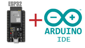
This time we are going to connect the encoder with ESP32 microcontroller board. We are going to use Arduino IDE to upload code to ESP32.
So for that you must have two things to be there on your computer system.
If you learn what this two points is just click the text you will be find how to make ready your Arduino IDE to program ESP32.
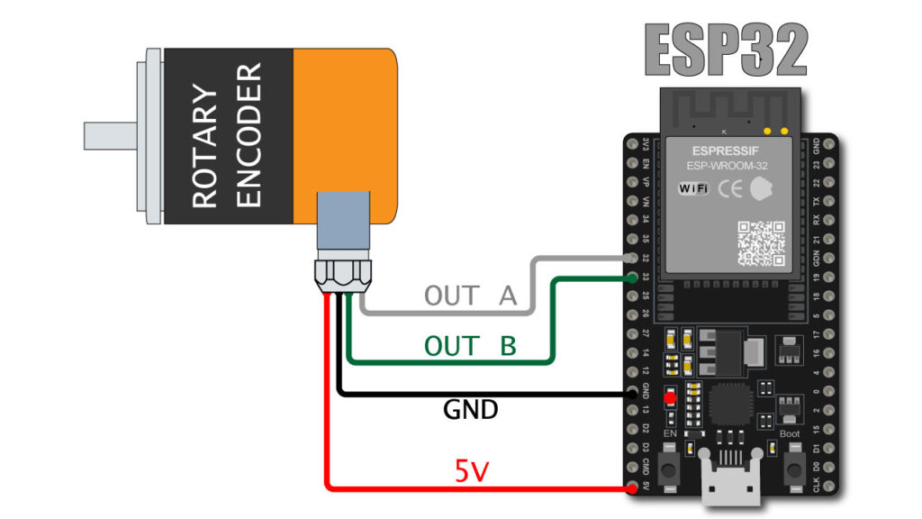
Wiring of Optical encoder and ESP32
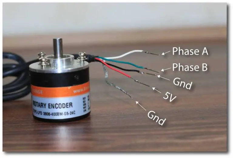
Here I am using orange make rotary encoder which have 400 pulse per revolution
Below you can see the wire details of encoder
WHITE : OUTPU – A
GREEN : OUTPUT – B
BLACK : GND
RED : +5V DC
SHIED : GND
connect optical rotary encoder with ESP32 as per below
WHITE (OUT A) : PIN 32
GREEN (OUT B) : PIN 33
RED : 5V
BLACK + SHIELD : GND
CODE
#define ENCODER_A 32 // Pin for Encoder A
#define ENCODER_B 33 // Pin for Encoder B

volatile int encoder_value = 0; // Global variable for storing the encoder position

void encoder_isr() {
  // Reading the current state of encoder A and B
  int A = digitalRead(ENCODER_A);
  int B = digitalRead(ENCODER_B);

  // If the state of A changed, it means the encoder has been rotated
  if ((A == HIGH) != (B == LOW)) {
    encoder_value--;
  } else {
    encoder_value++;
  }
}

void setup() {
  Serial.begin(115200); // Initialize serial communication
  pinMode(ENCODER_A, INPUT_PULLUP);
  pinMode(ENCODER_B, INPUT_PULLUP);

  // Attaching the ISR to encoder A
  attachInterrupt(digitalPinToInterrupt(ENCODER_A), encoder_isr, CHANGE);
}

void loop() {
  Serial.println("Encoder value: " + String(encoder_value));
  delay(100);
}
Above is the code to display the encoder value on serial monitor.
Connect the esp32 with USB and upload the code to the ESP 32
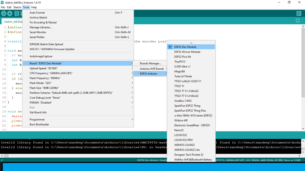
Make sure your board selection is must be same as visible in above image.
After uploading code to ESP32, open serial monitor
and rotate encoder shaft you can see the value increase if you rotate encoder in clock wise direction, and value decrease if you rotate in counter clockwise direction.
If value are showing reverse means giving -ve value for clockwise motion.
you can reverse the “GREEN” & “WHITE” wire.
OR
you can just change the first two line of code
#define ENCODER_A 32 // Pin for Encoder A
#define ENCODER_B 33 // Pin for Encoder B
VIDEO
Here is the video of live encoder value on IDE serial monitor