ESP32 IOT based Home Automation Project
ESP32 IOT based Home Automation Project
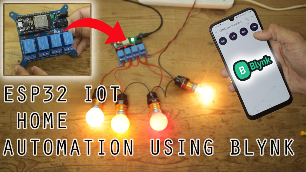
Hello friends In this post we will learn how to make a ESP32 IOT based Home Automation project using Blynk 2.0.
This days we here lots about IOT, IOT stands for Internet of things.
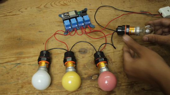
In this project we build a system using ESP32 and internet so that we can control heavy loads of out home like, LIGHTS, FANS, AC, etc.
We prepare a PCB for this project for more professional approach, you can also build it in Zero PCB
but I will recommend yo to go for custom PCB because HIGH voltage is involve in this project there is more chances of miss happen in home made ZERO PCB.
If you think PCB are costlier option then you are wrong try ALLPCB PCB prototyping service and you will never regret they offer high quality PCB in very affordable rated.
We are going to use Blynk IOT Cloud as IOT platform in this project.
So lets move further in the project first we will se what components we required to build ESP32 IOT based Home Automation Project
Components Required
| 1 | ESP32 DEV Board | 1 | https://amzn.to/3LhxIPH |
| 2 | Custom PCB | 1 | ALLPCB |
| 3 | 5V DC Relay HE JQC3FC | 4 | https://amzn.to/3Ll1m6L |
| 4 | 5MM DC Power Jack | 1 | https://amzn.to/3yuevmm |
| 5 | 16 Pin IC Base | 1 | https://amzn.to/3YGY5Sc |
| 6 | ULN2003 IC | 1 | https://amzn.to/3JxXZrT |
| 7 | FR207 Diode | 1 | https://amzn.to/402TE5d |
| 8 | 5mm Green LED | 1 | https://amzn.to/3l4RQKr |
| 9 | 3mm Red LED | 4 | https://amzn.to/3l4RQKr |
| 10 | 3Pin 5.08 pitch PCB terminal | 4 | https://amzn.to/428tIHi |
| 11 | 220 ohm resistor | 5 | https://amzn.to/3l0P0pT |
| 12 | LM7805 T0252 | 1 | https://amzn.to/3T63125 |
Circuit Diagram
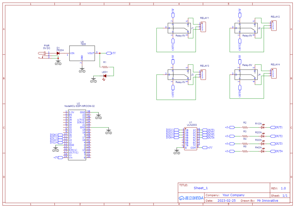
Below is the circuit diagram for ESP32 IOT based Home Automation Project.
I have used ESP32 board because obviously it have WIFI capability so we can connect it via internet and send command to turn load ON & OFF via Blynk IOT cloud.
Also I have used ULN2003 IC it is array of seven NPN Darlington transistors, the output voltage level of digital pins of ESP32 is limited to 3V so it is not advisable to turn 5V relay ON through this pins.
So here ULN2003 make our work easy, ESP give digital inputs to ULN2003 and ULN2003 turn on Relay respectively.
I have used LM7805 SMD linear voltage regulator to make sure to get regulated 5V supply of ESP32 ANS Relay coil.
I have also used FR207 diode to protect circuit from cross polarity, also used on 5mm Green led to indicate POWER is available at PCB.
3mm Red LED is used one for each relay this LED indicate the state of relay, if LED is on means Relay is on vice versa.
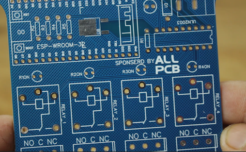
Custom PCB


I have prepared the PCB design from the above circuit diagram, as I said earlier this project involves High Voltage so I don’t want to take any risk and want to go in professional way so I prepared this PCB.
So now you think PCB may increase the price of project so I will tell my friend you are wrong ALLPCB offers very cheap rates for high quality PCB with very fact production time.
They have offer of 0$ for PCB prototyping
Just visit ALLPCB and upload your Gerber file to order PCB.
if you want to know how to order PCB watch the video in this post.
Below is the link of PCB and schematic
https://oshwlab.com/sharmaz747/esp32-home-automation-shield
Preparing PCB


After ordering the PCB it will arrive at my door step in just one week.
ALLPCB is very fast in PCB production and there shipping partner are also known for quick deliver.
As soon as I open the PCB I wass fully satisfied with the quality of PCB they also send some free goodies along with the PCB.
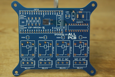
So now our PCB arrived its time to solder all the components on PCB.
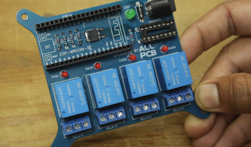
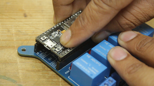
After completing the soldering process we will place the ESP WROOM 32 on it and ULN2003 IC
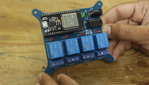
Finally our PCB is ready now its time to configure the software part.
We are using Blynk app in this project to turn the relay ON and OFF
Blynk IOT setup for ESP32 based Home Automation Project
There are basically three step to complete whole Blynk IOT setup
- Configuring Blynk web setup (getting firmware key & setting widget)
- Uploading code to ESP32 (uploading code using Arduino IDE )
- Configuring Blynk mobile app (Wifi credential and app widget)
Configuring Blynk web setup
So as of now we have ready with our PCB all components are soldered on the PCB, ESP32 board is also placed on PCB.
Now time to prepare Blynk IOT dashboard and configure Blynk Mobile app, so that we can control the load connected the PCB from anywhere via internet.
For that first of all we need to go Blynk IOT Cloud login page
you will get this type of page where you have to login or register yourself on Blynk IOT cloud it is pretty easy and straight forward.
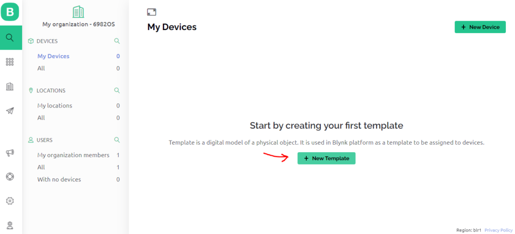
After you login Successfully you will get this type of startup page. here you have to click on +New Template
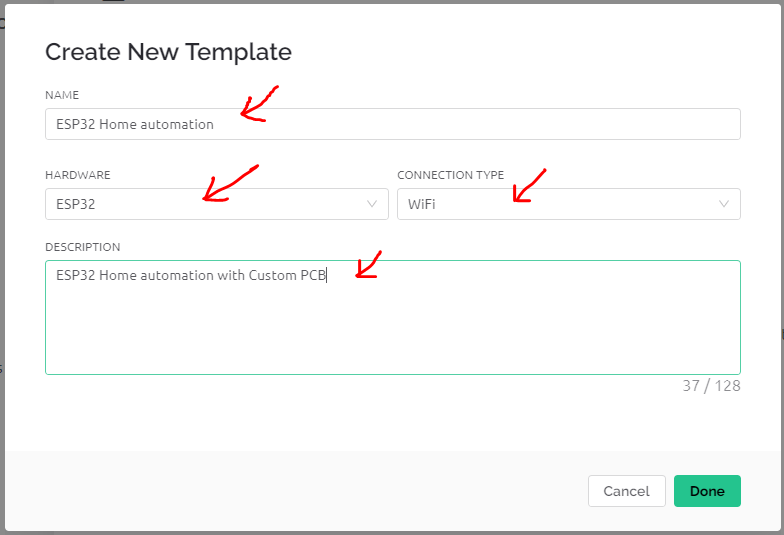
After clicking on +New Template you where ask to fill some basic information
like template name , Hardware type I have selected ESP32, Connection type WIFI, and added a small description at last click on Done.
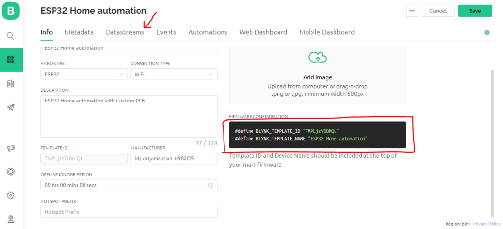
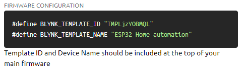
As we click on done our Template is ready first thing we have to do no down or copy past the two line of code highlighted in red box we will need it while uploading code to ESP32 Board.
After that click on Datastreams
Then click on +New Datastream and select the Virtual Pin
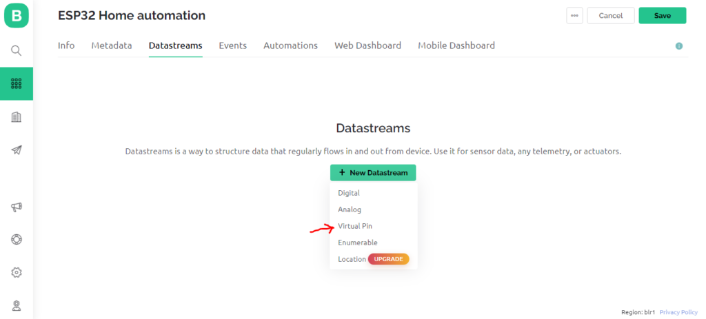
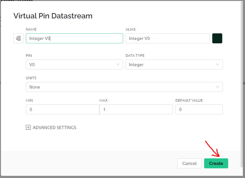
After clicking on virtual Pin we will get this type of window where we have define virtual pin.
As we are using relay to turn on and off we will select DATA TYPE as Integer.
MIN & MAX Value will 0 & 1
DEFAULT VALUE will be 0
After that click on create in this way our a virtual pin is created
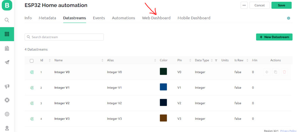
In the same way we have created four virtual pins because we have 4 relay to be controlled.
now time to create dash board from where we will control the relay on PCB. Simply click on web Dashboard
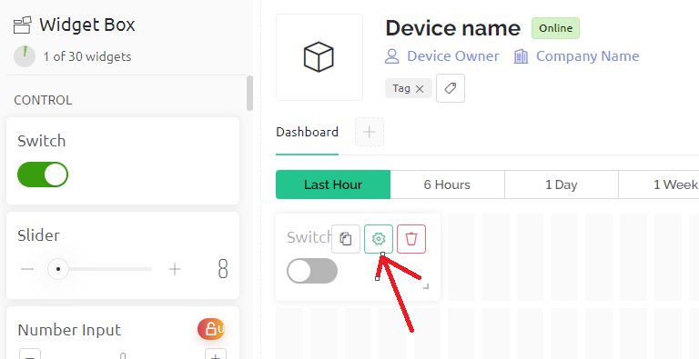
In dashboard option we have to drag and drop the Switch widget from left to right we need four of this switch.
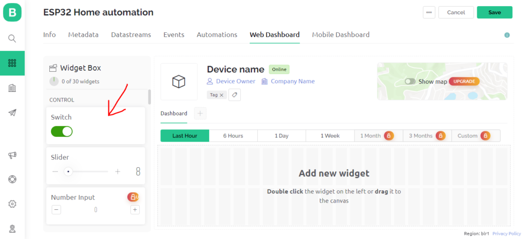
After placing the Switch widget we need to configure it correspondence to the previously created virtual pins for that simply click on setting icon on the widget.
I have name the first switch as Relay 1 as this switch oprates the relay 1 and in Datastream option I have selected V0 virtual pin for this switch. keeping other setting as it is click on save.
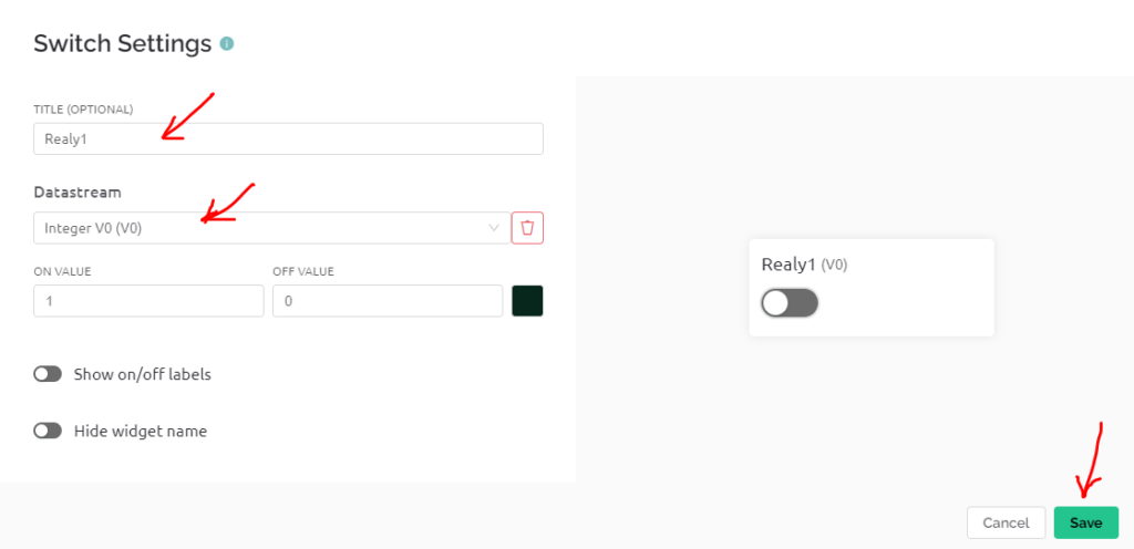
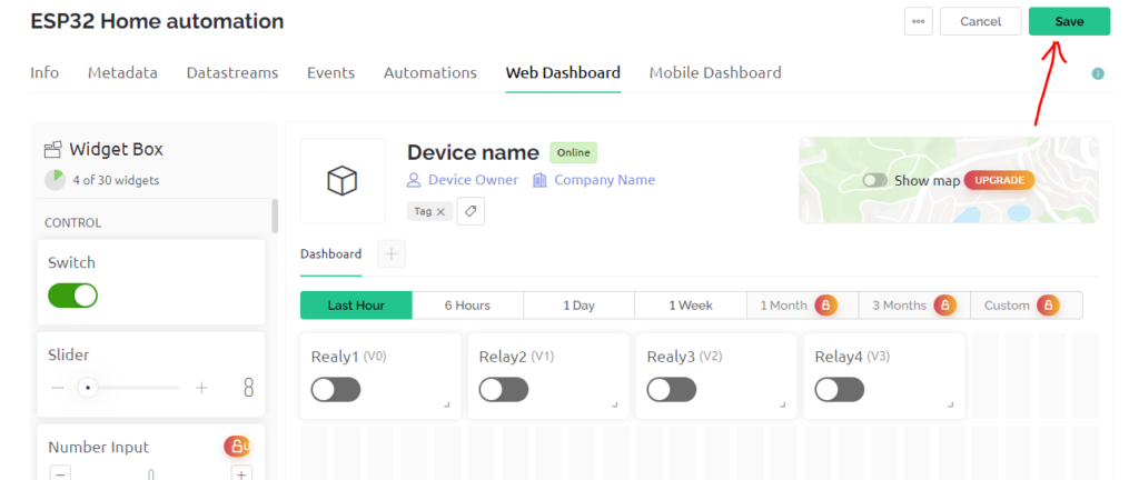
In the same way I have created 4 switch correspondence to each relay on our PCB.
After completing this part click on Save.
our web dashboard setup is completed not we left two more steps.
- uploading code to Esp32
- Configuring Blynk mobile app (wifi credential will be done in this step)
Now time to upload code to ESP32
do not close the blynk window and open the Arduino IDE.
Uploading code to ESP32
First off all we need a Blynk library to be install to move further
download the library from the link given below.
https://github.com/blynkkk/blynk-library
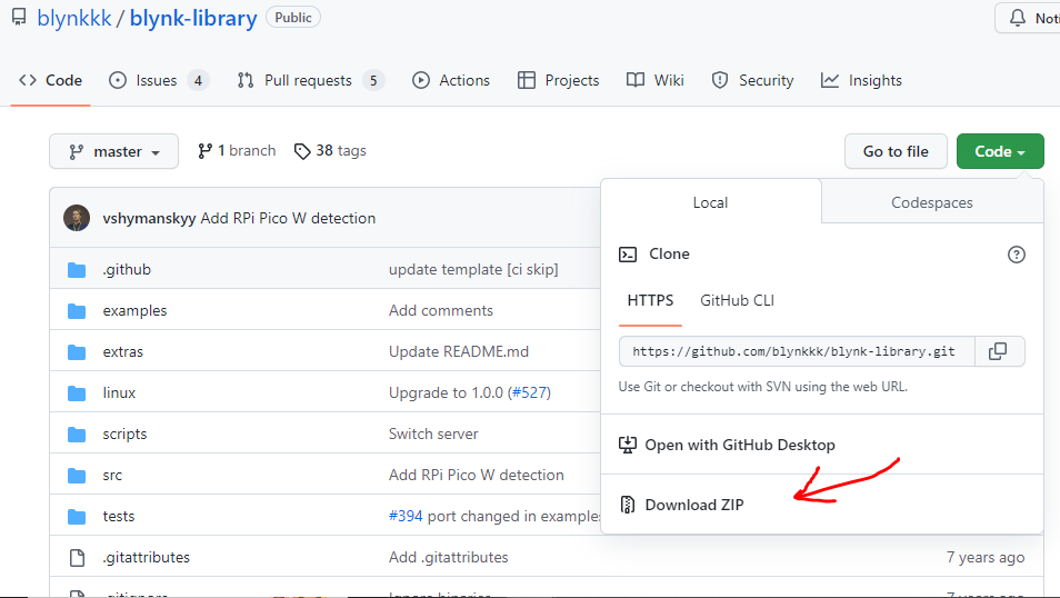
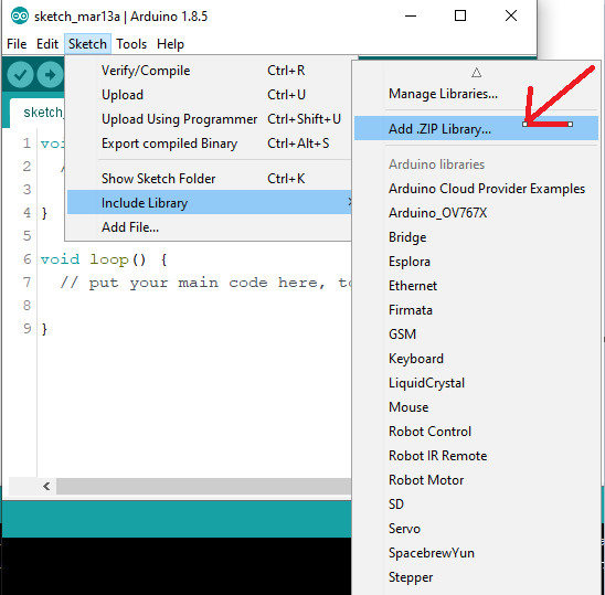
After downloading the zip file open the Arduino IDE, go to the Sketch option click on include Library and finally click on Add .ZIP Library.
Then after brows the recently downloaded library in zip format and complete the library installation process.
after that you have successfully installed the Blynk library in Arduino IDE.
Now go to the File option click on Example and look for Blynk now click on Blynk.Edgent and finally click on Edgent_ESP32

Now have the basic code open we need to add some lines as per our requirements
below is the final code for our project to control 4 relays.
#define BLYNK_TEMPLATE_ID "TMPLjzYOBMQL"
#define BLYNK_TEMPLATE_NAME "ESP32 Home automation"

#define BLYNK_FIRMWARE_VERSION        "0.1.0"

#define BLYNK_PRINT Serial
//#define BLYNK_DEBUG

#define APP_DEBUG

// Uncomment your board, or configure a custom board in Settings.h
//#define USE_ESP32_DEV_MODULE
//#define USE_ESP32C3_DEV_MODULE
//#define USE_ESP32S2_DEV_KIT
//#define USE_WROVER_BOARD
//#define USE_TTGO_T7
//#define USE_TTGO_T_OI

#include "BlynkEdgent.h"

BLYNK_WRITE(V0){
  int pinValue = param.asInt();
  digitalWrite(27,pinValue);

}

BLYNK_WRITE(V1){
  int pinValue = param.asInt();
  digitalWrite(26,pinValue);

}

BLYNK_WRITE(V2){
  int pinValue = param.asInt();
  digitalWrite(14,pinValue);

}

BLYNK_WRITE(V3){
  int pinValue = param.asInt();
  digitalWrite(12,pinValue);

}

void setup()
{
   pinMode(27,OUTPUT);
  pinMode(26,OUTPUT);
  pinMode(14,OUTPUT);
  pinMode(12,OUTPUT);
  Serial.begin(115200);
  delay(100);

  BlynkEdgent.begin();
}

void loop() {
  BlynkEdgent.run();
}
Explanation of above code
#define BLYNK_TEMPLATE_ID "TMPLjzYOBMQL"
#define BLYNK_TEMPLATE_NAME "ESP32 Home automation"
This first two line of code you have to replace with your line which we have previously copy and pested while setting Blynk IOT web setup
Here we have created even for our four virtual pin each will operate a individual relay, here we define the pin at which relay is connected.
BLYNK_WRITE(V0){
  int pinValue = param.asInt();
  digitalWrite(27,pinValue);

}

BLYNK_WRITE(V1){
  int pinValue = param.asInt();
  digitalWrite(26,pinValue);

}

BLYNK_WRITE(V2){
  int pinValue = param.asInt();
  digitalWrite(14,pinValue);

}

BLYNK_WRITE(V3){
  int pinValue = param.asInt();
  digitalWrite(12,pinValue);

}
At last we define the pinMode in Void setup function.
After completing this upload the code to ESP32 with proper board and port selected.
void setup()
{
   pinMode(27,OUTPUT);
  pinMode(26,OUTPUT);
  pinMode(14,OUTPUT);
  pinMode(12,OUTPUT);
  Serial.begin(115200);
  delay(100);

  BlynkEdgent.begin();
}
if you don’t know how to upload code to ESP32 using Arduino IDE read this article.
How to program ESP32 using Arduino IDE
As of now our 2 steps are completed now we will move towards 3rd and final step
Configuring Blynk mobile app
Configuring Blynk mobile app is necessary to control relay on and off from Mobile phone and to pass WIFI credential to the ESP32
First off all download and login in Blynk app from the same ID you have logged in Blynk web IOT cloud.
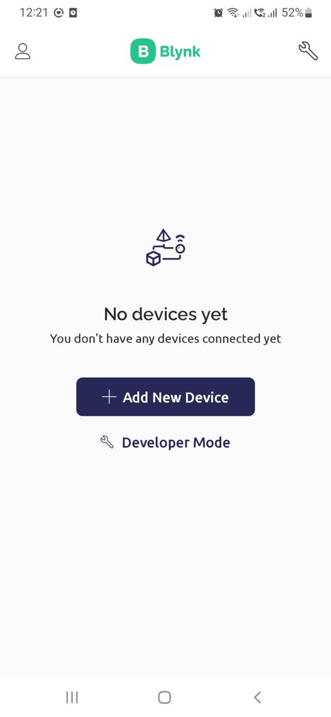
After login click on Add New Device
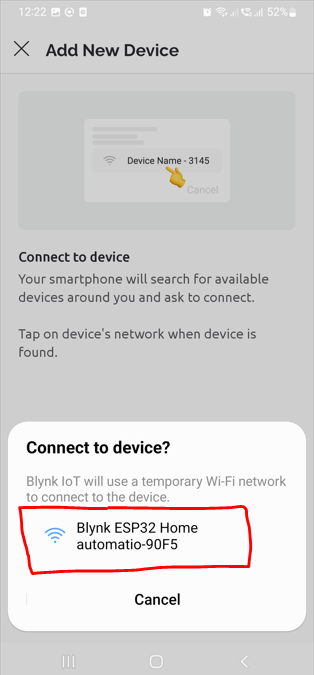
After continue further using option connect nearby system place you ESP32 near to you mobile the mobile app will automatically find the ESP32 .
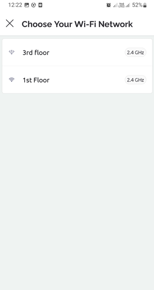
Click on the available WIFI device to connect with.
Now choose the WIFI router of your choice to connect with.
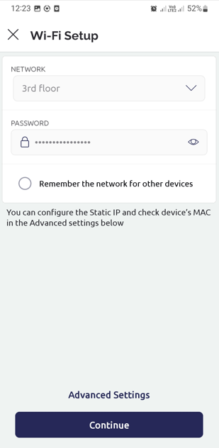
Here you have to enter the password of your wifi router in this way ESP32 is ready to connect with your house WIFI router.
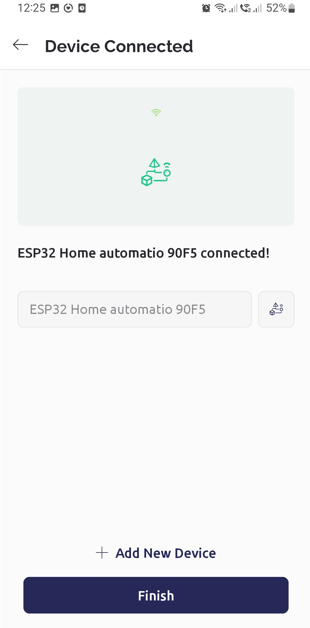
Now we have connected with device now click on Finish
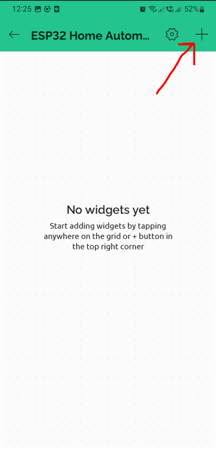
Now here we have to add Switch widget same as we have done for web.
Click on + icon and select the Switch option.
Now here I have set 4 switch widget for the four relay with virtual pin V0, V1, V2 & V3
Most important set MODE in Switch otherwise relay will on when widget keep clicked if we release switch relay will off.


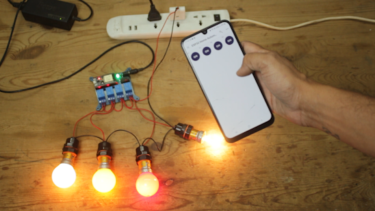
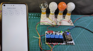
That’s it our ESP32 IOT home automation project is ready just click on the widget to turn on and off relay.
Finally all the necessary step is completed, now we can connect the real load to the PCB and turn them ON and OFF from our Mobile or computer.