How to Control DC motor with DRV8833
drv8833 motor driver ic tutorial
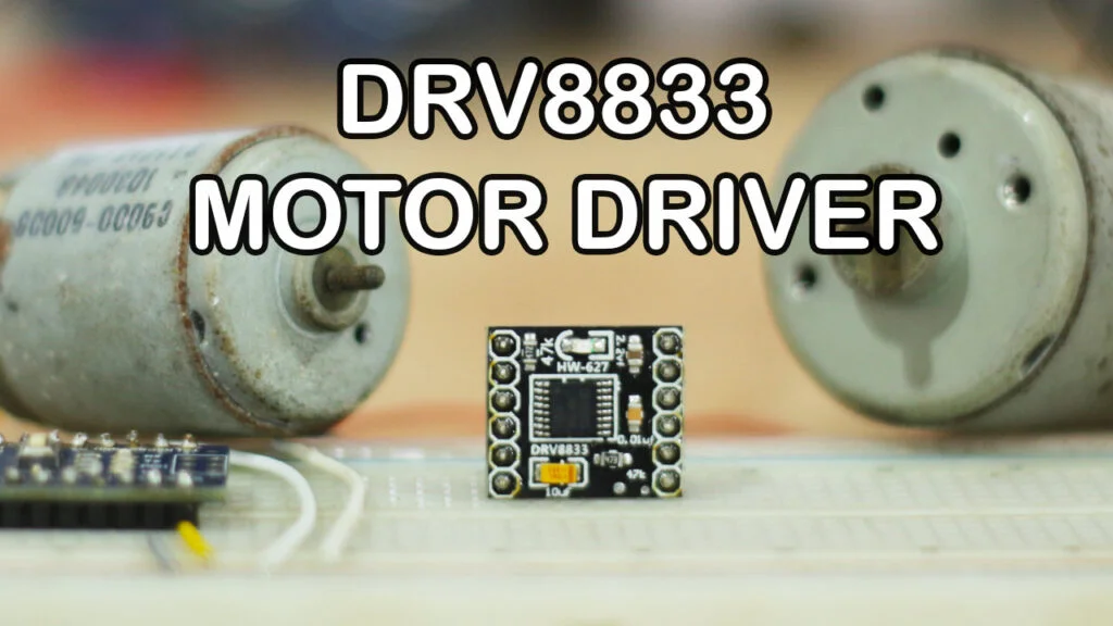
Hello, friends in this post we will learn about DRV8833 and how to control DC motor using DRV8833 motor driver.
DRV8833 is dual H bridge motor driver, it can control upto 2 DC motor or one stepper motor.
Yes, there are many other H bridge DC motor driver among them L293D & L298N are the most famous one. so what is the importance of DRV8833.
So the traditional driver like L293D & L298N as based on BJT, which reduce the efficency due to heat losses.
BUT this DRV8833 is based on MOSFET which is higly efficent and generate very less heat this makes DRV8833 relaible DC motor driver.
Also, DRV8833 does not need separate control and power supply.
So let us see some specification and pinout of DRV8833
DRV8833 PINOUT
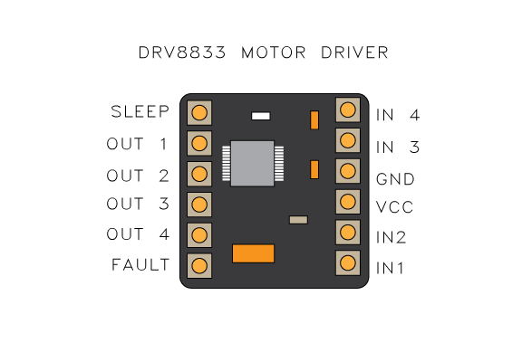
- SLEEP = This pin is to enable and disable the DRV8833 driver, by default DRV8833 is enable
leave this pin as it is floating if you are not planning to enable and disable the function. - OUT 1 = Power output A
- OUT 2 = Power output A
- OUT 3 = Power output B
- OUT 4 = Power output B
- FAULT = This pin gets low if over current, over temperature, or Undervoltage detected by DRV8833
IC and pin is floating in a healthy condition.
If you need to monitor the fault condition need to connect an external pullup resistor. - IN 1 = Input 1 for channel A
- IN 2 = Input 2 for channel A
- VCC = DC power supply (2.7V to 10.8 V)
- GND = ground
- IN 3 = Input 1 for channel B
- IN 4 = Input 2 for channel B
Electrical Specifications of DRV8833
Motor voltage = 2.7V to 10.8V
Logic Voltage = 3V to 5V
Current = 1.2 Amps per channel
Max. Current = 2 Amps per channel
Motor channel = 2
DRV8833 motor connection
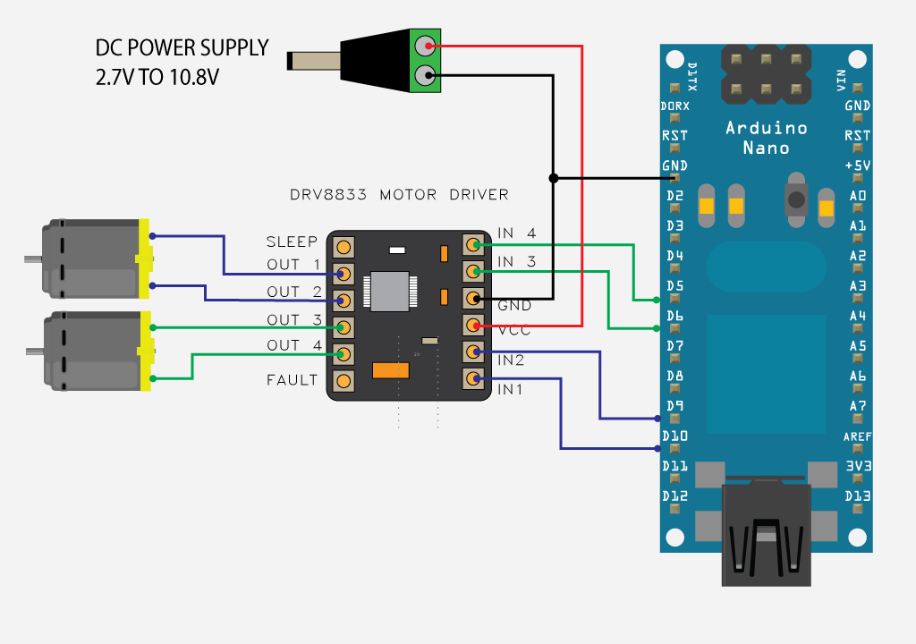
Set up the wiring connection as per the wiring diagram shown in the picture.
IN1 — D10 (PWM)
IN2 — D9 (PWM)
IN3 — D6 (PWM)
IN4 — D7 (PWM)
As we can see I have selected all input pins are PWM capable so that we can control SPEED of DC motor as well.
Arduino CODE for DRV8833
below is the Arduino code to run 2 DC Motor using DRV8833 motor driver IC
The code run both motor individually one by one.
// MOTOR 1
#define IN1 10
#define IN2 9

// MOTOT 2
#define IN3 6
#define IN4 5


void setup() {
 pinMode(IN1, OUTPUT);
 pinMode(IN2, OUTPUT);
 pinMode(IN3, OUTPUT);
 pinMode(IN4, OUTPUT);

}

void loop() {

 // motor 1 run 50% speed in FWD for 5 seconds

  analogWrite(IN1,255/2);
  digitalWrite(IN2, LOW);

  delay(5000);

// motor 1 stop for 3 seconds

  digitalWrite(IN1,LOW);
  digitalWrite(IN2, LOW);
  delay(3000);

 // motor 1 run 50% speed in RVS

  analogWrite(IN2,255/2);
  digitalWrite(IN1, LOW);

delay(5000);

 digitalWrite(IN1,LOW);
  digitalWrite(IN2, LOW);
  delay(3000);

 // motor 2 run 50% speed in FWD for 5 seconds

  analogWrite(IN3,255/2);
  digitalWrite(IN4, LOW);

  delay(5000);

// motor 2 stop for 3 seconds

  digitalWrite(IN3,LOW);
  digitalWrite(IN4, LOW);
  delay(3000);

 // motor 2 run 50% speed in RVS

  analogWrite(IN4,255/2);
  digitalWrite(IN3, LOW);

delay(5000);

 digitalWrite(IN3,LOW);
  digitalWrite(IN4, LOW);
  delay(3000);

}
