How to make LM317 based Variable Voltage regulator
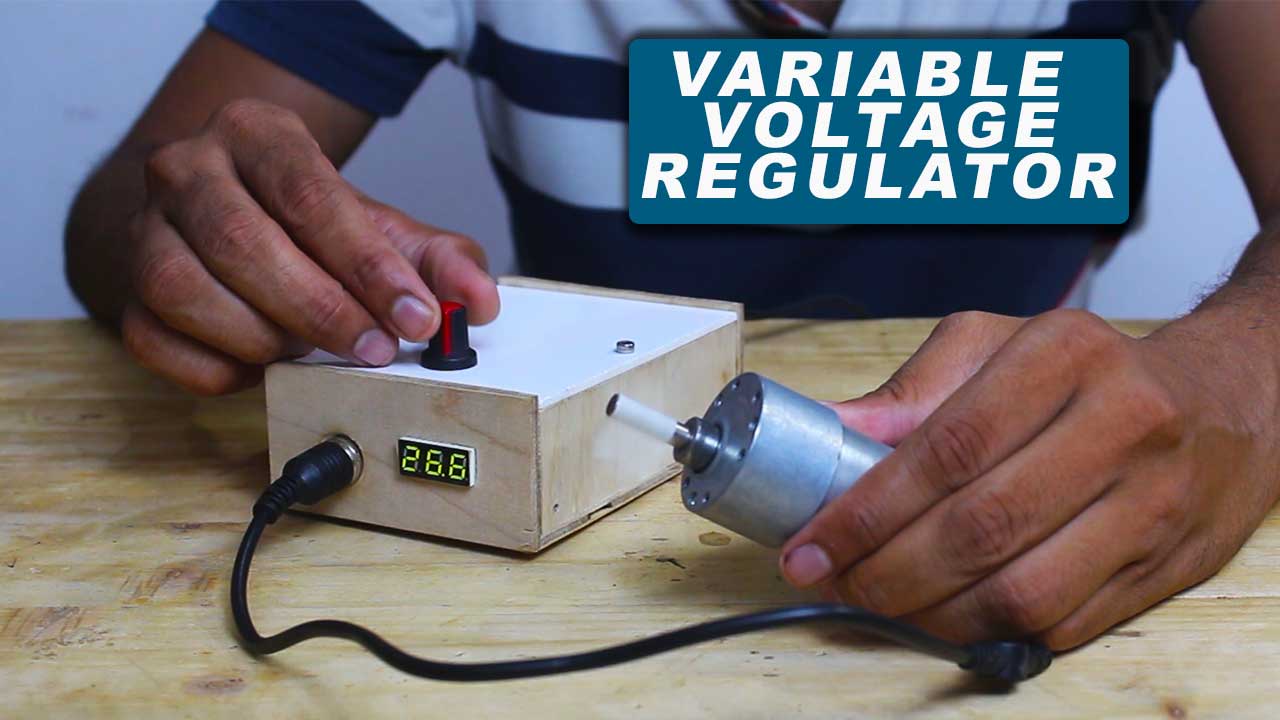
Hello makers in this post we’ll learn how to make LM317 based variable voltage regulator circuit module.
So a obvious question come in your mind what is variable voltage regulator circuit is ?
A circuit which regulate the voltage in some range like 5V to 24V dc with respect to constant input voltage is what we called a variable voltage regulator.
Some times we need different level of voltage for different type of applications like sometimes we need 5V dc for sensors, 9V or 12V for motors etc.
So we need different different rating of power supply which can fulfill our job or what if If we can use only one power supply unit for all type of voltage levels.
Yes this is possible with Variable voltage regulator it can regulate voltage for you in range of 1.25V to 35V.
And this voltage regulator circuit is quit easy to build on our self by using LM317 voltage regulator IC.
In this post I’ll show you step by step procedure how I build my own LM317 based variable voltage regulator.
which can convert 230VAC supply into 1.25V to 24V DC.
So lets begin the tutorial first we’ll see the list of components required.
VIDEO of LM317 based variable voltage regulator
Here is the complete video of this project you can watch this before continue on post
Components Required
- LM317
- 230V to 12-0-12 Transformer
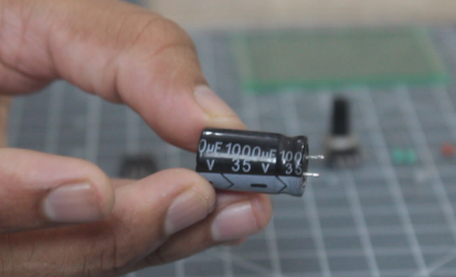
- 1000uF 35V capacitor
- 1uF 50V or 35V capacitor
- 0.1uF capacitor
- 50K potentiometer
- 2.5K ohm Resistor
- Voltage indicator display
- Alligators Clips
- ON OFF switch
- Zero PCB to solder all components on it
- A box in which all components get placed
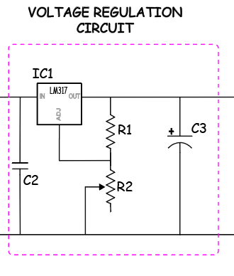
Circuit Drawing
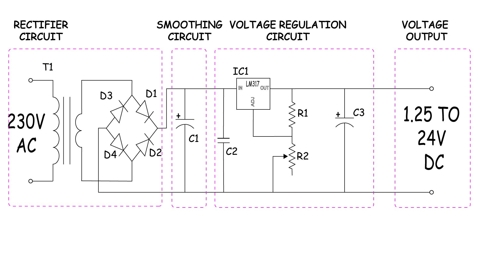
As you can see above given image is the basic circuit design of Variable voltage regulator using LM317 IC.
We step by step understand the circuit, if you have noticed I have not mention any components ration in above circuit.
because components rating are different for different design so I teach you how to find out ratings of components based on your need or system deign.
I divide the whole circuit in Four part this will help us to understand circuit very easily.
- Rectifier circuit
- Smoothing circuit
- DC Voltage regulator circuit
- Variable voltage output
I have prepared the whole circuit on Zero PCB but I also designed its Gerber file so that you can order PCB and make your project more professional.
Because PCBWAY have very affordable rates for PCB manufacturing like 5$ for 10 PCB boards so why not you have to try there service
PCBWAY not only produce FR-4 and Aluminum boards, but also advanced PCB like Rogers, HDI, Flexible and Rigid-Flex boards, with very reasonable price. Online instant quote page – https://www.pcbway.com/orderonline.aspx
Online Gerber viewer: https://www.pcbway.com/project/OnlineGerberViewer.html
PCB manufacturing process: https://www.youtube.com/watch?v=_GVk_hEMjzs

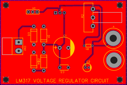
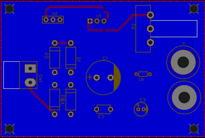
You can download Gerber file for PCB from here
Rectifier Circuit
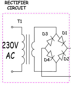
As you can see in circuit drawing the first step is to convert AC voltage into DC which is also known as rectifier circuit.
If you are readily giving DC supply as input to voltage regulator IC then you can skip 1st and 2nd circuit.
Obviously we need low voltage level so first we need to step down our main 230V AC supply to 24V AC.
for that here I have used a 230V to 12-0-12 0 1Amps step down transformer.
Transformer have two windings primary and secondary.
we are giving 230V AC to the primary winding and it is step down to 12-0-12 voltage on secondary winding.
No we step down the input voltage but still this voltage is AC but we need DC voltage & its level is 24V DC.
To convert AC into DC we need a fullwave bridge diode circuit.
So we used here 4 nos. FR207 diode which convert 12-0-12 V AC to 24V DC.
FR207 can handle upto 2amps which is more than enough for us.
Basically your diode rating must higher than the Max secondary winding amps rating of transformer.
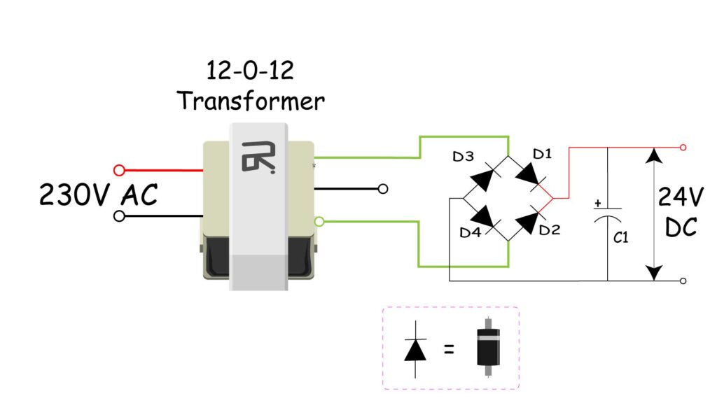
As per above image we can under stand that by giving 12V AC at junction of diode D3, D1 & D4,D2 we get +24V DC at junction of diode D1 & D2 and -24VDC at junction of diode D3 & D4.
Smoothing/Filter Circuit
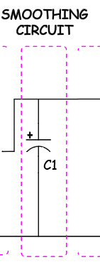
Now this freshly converted 24V DC is quite raw we need to smooth/filter it before using in circuit for this we need to add a capacitor.
Let see how to calculate the rating of this smoothing capacitor C1 refer previous image.
C\quad =\quad \frac { I *T }{ U } Where
C = Capacitance value
I = Amp Value
T = Half cycle time that is (10ms for 50hz supply)
U = Capacitor discharge voltage
Now we need to find out he value of C which is our capacitance value of capacitor.
here we can take
I = 1 amps (max load of circuit)
T = 10 ms (half cycle time for 50hz supply)
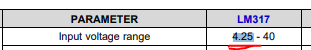
U = 19.75V (capacitor discharge value = V – min input voltage level for LM317 IC )
that is 24 – 4.25 = 19.75
By putting all values in formula we get
C\quad =\quad \frac { 1\quad *\quad 10m }{ 19.75 } \quad =\quad 0.506mF\quad =\quad 506uFSo we get the value 506uF so we can take 1 rating higher that is 1000uF and voltage of capacitor must be higher than the circuit voltage level so we selected 35V
Our final selection of capacitor is 1000uf 35V electrolytic capacitor.
Upto here our rectifier & smoothing circuit is competed lets move further
Voltage regulator circuit
Till here we get a smooth filtered 24V DC from rectifier via smoothing circuit now all the magic going to happen here & LM317 is magician of this show.
In this voltage regulator circuit we have 5 components
1. LM317
2. R1 resistor
3. R2 Variable resistor(pot)
4. C1 capacitor
5. C2 capacitor
Lets see how to select there ratings
LM317 IC
LM317 IC is the linear voltage regulator IC which Three terminals ADJUST, OUTPUT, INPUT
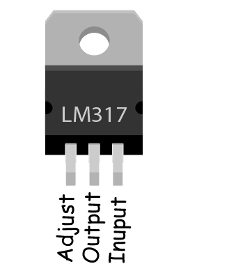
Input voltage range = 4.25 to 40 V DC
Max Amps capacity = 1.5 Amps
Output voltage range = 1.2 to 37 V DC
C1 & C2 capacitor values are 0.1uF ceramic capacitor & 1uF Electrolytic capacitor respectively.
Now we need to calculate the value is Resistance R1 and R2 which is very important here below is the formula to calculate there values.
{ V }_{ out }\quad =\quad 1.25(1+\frac { { R }_{ 2 } }{ { R }_{ 1 } } )Vout = output voltage (that is 24V)
R1 = Value of resistor R1
R2 = Value of resistor R2
Here in my case I have 50K ohm pot as R2 so have to choose the resistor R1 accordingly so I simplify the equation as.
{ R }_{ 1 }\quad =\quad \frac { 1.25*{ R }_{ 2 } }{ { V }_{ OUT }-1.25 } { R }_{ 1 }\quad =\quad \frac { 1.25*50000 }{ 25-1.25 } { R }_{ 1 }\quad =\quad 2600\quad =\quad 2.6K\Omega So Finally we have the value for resistors and capaciotors are
R1 = 2.6 K ohm
R2 = 50 K ohm pot
C1 = 0.1 uF ceramic capacitor
C2 = 1uF electrolytic capacitor
So now our final circuit will look like this
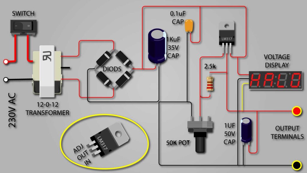
Now we need to attach some pins for output so that we can connect our load there.
The positive terminal we get from LM317 itself and Negative terminal we can get from negative terminal of 1uf Capacitor
By rotating the Pot we get the variable voltage at output pin. LM317 heating rate is directly proportional to the difference between input voltage and output voltage so its advisable to maintain voltage level difference as low as possible.
I this way we have build our own LM317 based linear variable voltage regulator circuit module.
Hope you understand the concept very well this will help you to design your own circuit with concept clear in mind.