DIY PCB inspection Machine | PCB Microscope | Arduino project
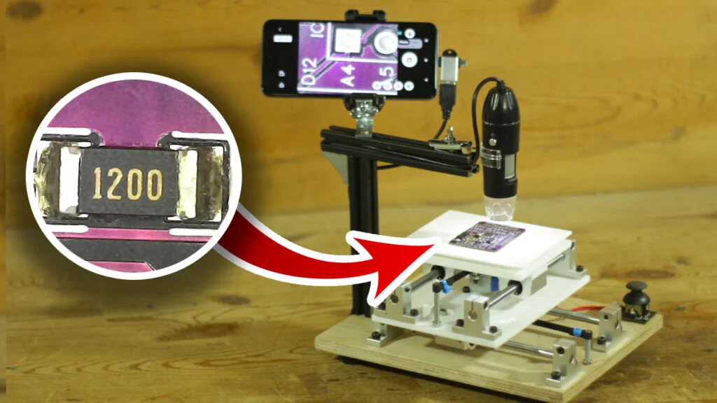
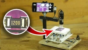
Hello, friends! In this project, I built a motorized platform for PCB inspection that makes examining circuit boards much easier and more precise.
I used a budget-friendly microscope available on Amazon, which I mounted onto the platform for clear and detailed views of the PCB.
The platform is powered by two 12V DC mini stepper motors (28BYJ-48) paired with A4988 stepper drivers, all controlled by an Arduino Nano.
For smooth and intuitive control, I added a joystick that allows you to move the platform left, right, forward, and backward with ease.
This project turned out to be highly impressive.
Unlike manual inspection, where moving the PCB by hand can cause scratches and unstable results, this motorized setup provides a smooth, scratch-free inspection experience.
It’s incredibly satisfying to control the axis with the joystick, making the process not just efficient but also fun!
Check out the video to see this machine in action and how it can revolutionize your PCB inspection process!
VIDEO
MATERIAL LIST
- 12mm wooden base
- 8mm shaft holder 8qty
- 8mm linear bearing 4qty
- Timming belt
- 20x20alu. profile
- Arduino nano
- custom PCB
- Joystick
- Microscope
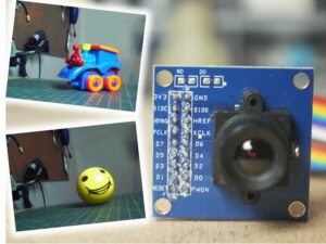
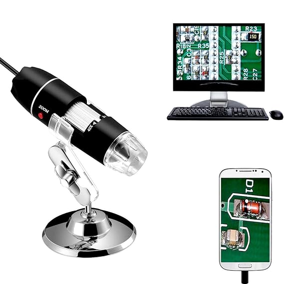
Microscope
I have used this microscope which is available in cheap on amazon
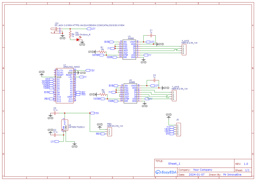
Circuit Diagram
Arduino code
#include <Arduino.h>
#include "BasicStepperDriver.h"
#include "MultiDriver.h"
#include "SyncDriver.h"

// Motor steps per revolution. Most steppers are 200 steps or 1.8 degrees/step
#define MOTOR_STEPS 500
// Target RPM for X axis motor
#define MOTOR_X_RPM 20
// Target RPM for Y axis motor
#define MOTOR_Y_RPM 20

// X motor
#define DIR_X 5
#define STEP_X 3

int xpin = A1;
int ypin = A0;

int xval = 0;
int yval = 0;

// Y motor
#define DIR_Y 6
#define STEP_Y 4

// If microstepping is set externally, make sure this matches the selected mode
// 1=full step, 2=half step etc.
#define MICROSTEPS 16

// 2-wire basic config, microstepping is hardwired on the driver
// Other drivers can be mixed and matched but must be configured individually
BasicStepperDriver stepperX(MOTOR_STEPS, DIR_X, STEP_X);
BasicStepperDriver stepperY(MOTOR_STEPS, DIR_Y, STEP_Y);

// Pick one of the two controllers below
// each motor moves independently, trajectory is a hockey stick
 MultiDriver controller(stepperX, stepperY);
// OR
// synchronized move, trajectory is a straight line
//SyncDriver controller(stepperX, stepperY);

void setup() {
    /*
     * Set target motors RPM.
     */
    stepperX.begin(MOTOR_X_RPM, MICROSTEPS);
    stepperY.begin(MOTOR_Y_RPM, MICROSTEPS);
    // if using enable/disable on ENABLE pin (active LOW) instead of SLEEP uncomment next two lines
    // stepperX.setEnableActiveState(LOW);
    // stepperY.setEnableActiveState(LOW);
}

void loop() {


xval = analogRead(xpin);
yval = analogRead(ypin);

if (xval>650){
controller.rotate(10, 0);
}

if (xval<400){
controller.rotate(-10, 0);
}

if (yval>650){
controller.rotate(0, -10);
}

if (yval<400){
controller.rotate(0, 10);
}


}

