How to make Arduino based digital Tachometer or RPM counter
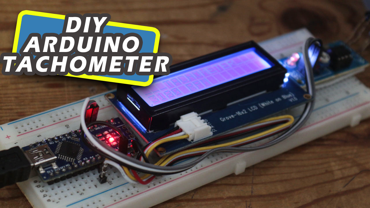
arduino based digital tachometer rpm counter
Hello makers in this post we will see how simple you can build a Arduino based digital tachometer or RPM counter
You can build this device quickly at home on your own, you only need few components listed below.
Component required
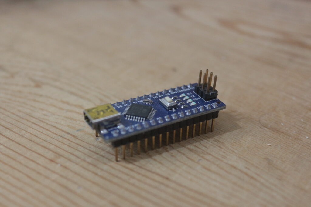
- Arduino Nano ( you can use UNO or Mega as well)
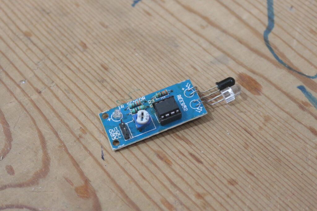
- IR Sensor module
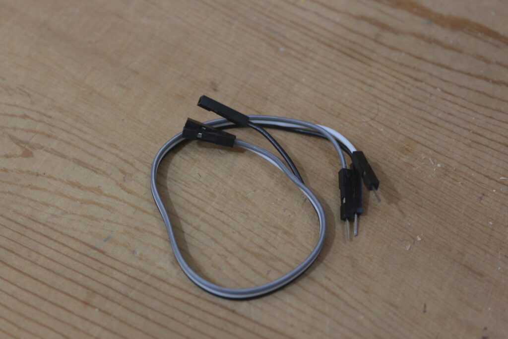
- some jumper wires
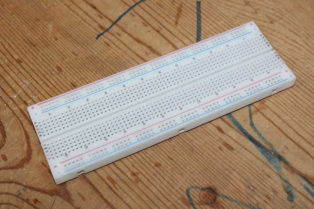
- Bread Board
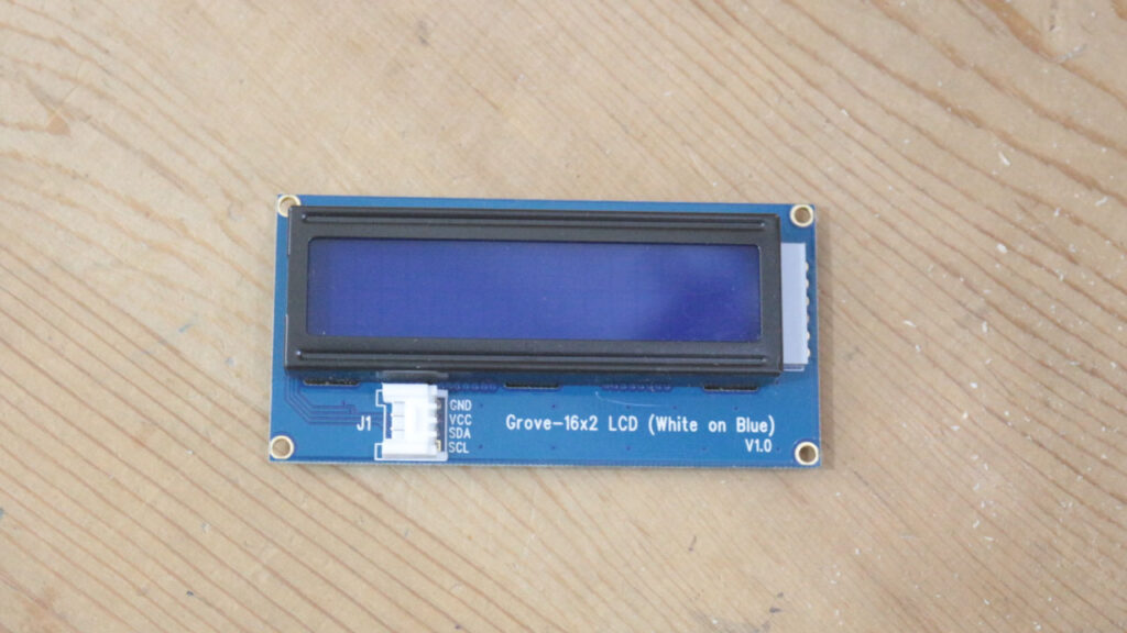
- 16 x 2 I2C display
Basics of how IR sensor works
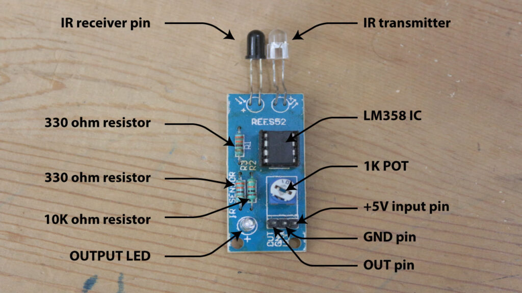
IR stands for infrared light, its non visible form of light. its wavelength is longer then visible light, so human eyes not able to see Infrared light.
Ir sensor module have two IR diode one is transmitting IR light and one is receiving IR light.
White surface reflect IR light and black surface absorb IR light.
When IR sensor module is powered on IR transmitter emit IR rays if any white object came in front of IR transmitter so IR rays reflect from that body and IR receiver receive this rays and generate a 5V digital output at output pin with the help of LM358 IC.
Range of IR sensor can adjust from 1K ohm pot available on board.
Now let we see how to build a digital Tachometer or RPM counter using IR sensor.
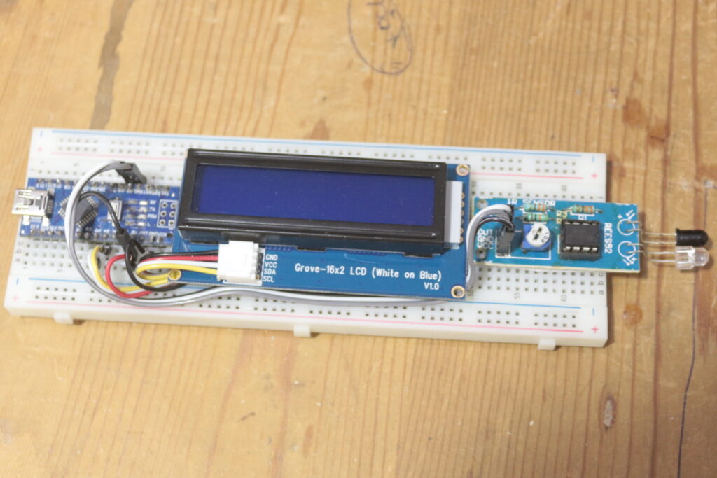
Circuit diagram of Arduino based digital Tachometer

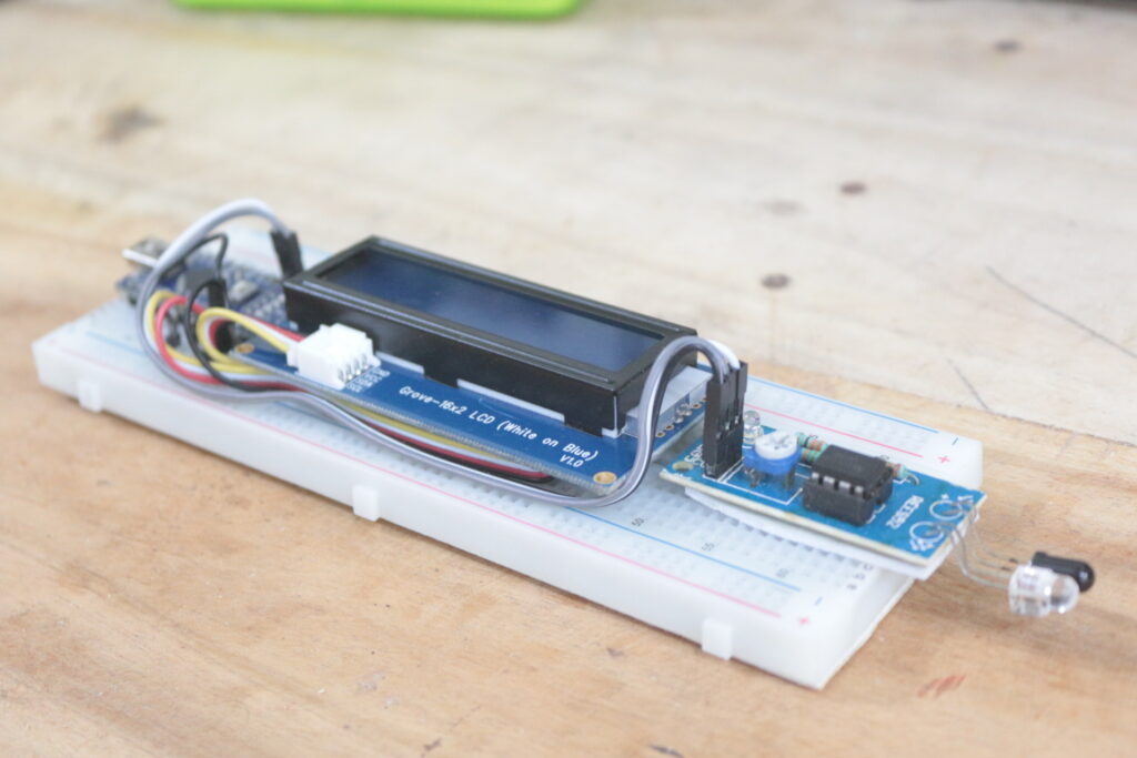
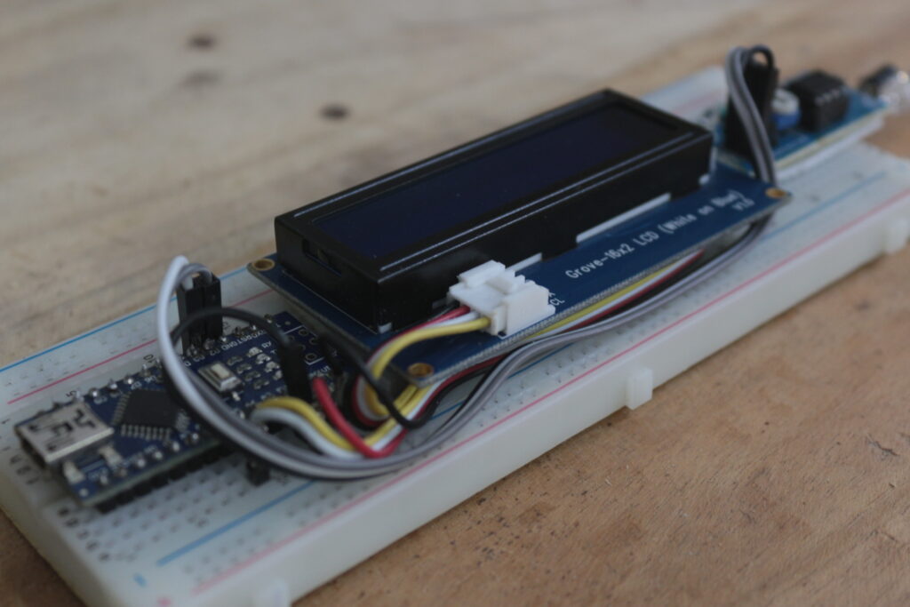
Do the wiring as shown in image wiring is very simple it can be done simply on breadboard.
Arduino code for arduino based tachometer
#include <Wire.h>
#include "rgb_lcd.h"
rgb_lcd lcd;
float value=0;
float rev=0;
int rpm;
int oldtime=0;
int time;

void isr() //interrupt service routine
{
rev++;
}

void setup()
{
lcd.begin(16,2);                //initialize LCD
attachInterrupt(0,isr,RISING);  //attaching the interrupt
}

void loop()
{
delay(1000);
detachInterrupt(0);           //detaches the interrupt
time=millis()-oldtime;        //finds the time
rpm=(rev/time)*60000;         //calculates rpm
oldtime=millis();             //saves the current time
rev=0;
lcd.clear();
lcd.setCursor(0,0);
lcd.print("___TACHOMETER___");
lcd.setCursor(0,1);
lcd.print(     rpm);
lcd.print(" RPM");
lcd.print("   ");
attachInterrupt(0,isr,RISING);

}
Video
You can watch the below video of arduino based tachometer in action.

Hey Sandeep,
How did you get this formula:
rpm=(rev/time)*900;
Wondering where the 900 came from. Per my knowledge, it should be 60,000.