Fire cracker remote using ESP node mcu
HI Guys! Today I will be showing you how to make Fire cracker remote using ESP node mcu
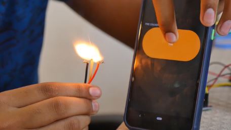
It’s one major advantage is that we can light fireworks from a safe distance… Its a easy project and you will only need a couple of minutes to build this ….This project uses the BLYNK IOT Software.
Let’s Get Started !!
Components required
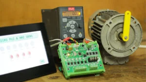
- Node MCU
- Breadboard
- Relay Module
Assembling
Set the LM2596 to 5v

Warning!! Make sure that the Output is 5v and not 12v Or else Your NodeMCU and Relay Will get Damaged
You can see a preset potentiometer on the board . with the help of a screwdriver turn it…
Set your multimeter to 20v and connect it to the output terminal to read the voltage… While setting up the Buck converter Make sure you are conning the mower supply to the input of the module and the terminal of Multimeter to the output of the module
If you don’t have a buck converter you can use power transistors Like LM7805 Voltage regulators which we do not have to adjust the voltage and does not require a Multimeter .. In its output it will give out constant 5v

circuit diagram for Fire cracker remote using ESP node mcu
Connect Everything according to the circuit diagram below
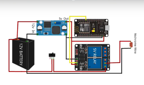
D4 Pin > Relay module
Buck Output + > Vin of NodeMCU & 5v of Relay module
Buck Output – > Gnd oog NodeMCU & Gnd of Relay Module
12v + > Input + of Buck & To the One terminal of relay
12v- > Input – of Buck & To the Nichrome wireThe middle terminal of relay module to > Nichrome wires Other end
Build the fuse
It is important to generate a fire to light the crackers … some types of checkers won’t burn themselves just by giving heat for like that crackers we need to build a fuse…
Note : If you are using crackers like Rocket etc… You don’t need to build a fuse just Nichrome wire is enough to light the Rocket
First we need a matchStick & Cut it half (The place containing the Phosphorus ) with a knife or a blade as shown below

Next Take two wires and tie each other with Nichrome wire as shown below

Tie one end of Nichrome wire to positive terminal and the other end to Negative terminal
Next Insert the Nichrome wire between the Matchstick which you have cutted in half

While inserting make sure that the nichrome wire is touching the region containing phosphorus.. Else it will not burn when the Nichrome wire Heats up
Our Circuit has been completed
NEXT Let’s go to the Programming Part
In this project we are using Arduino iot software .. So we need to setup the Arduino Software
So follow these steps without any mistakes
Setting up Arduino IOT Software
You can visit our tutorial how start using Arduino IOT software
You just basically have to create a button to ignite the fire work.
Code Upgrades
When you complete by creating the button in Arduino IOT Cloud platform.
time to move towards code in sketch editor

First we need to upgrade our codes. You should follow these steps correctly
Next , We need to define an output … In this project I am Using Digital Pin 4. In NodeMcu it is GPIO Pin 2.. So copy and paste the code below under the Void Setup…

Next , We need to define an output … In this project I am Using Digital Pin 4. In NodeMcu it is GPIO Pin 2.. So copy and paste the code below under the Void Setup…
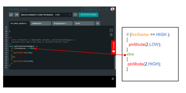
Next we need to add some code beneath [ void onfireStarterChanges() ] . Just copy the code below and paste it in the right place
Hurray! Programming is Completed
Next we need to upload code ( For that you need to install Arduino create agent ) It is pretty simple step the software will tell you what to do) … after installing select the COM and Board as NodeMCU 1.0 And Hit the Upload Button

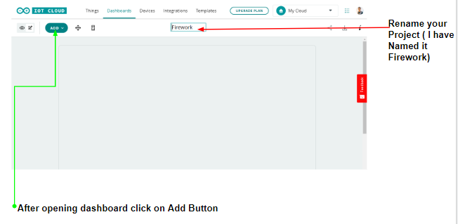
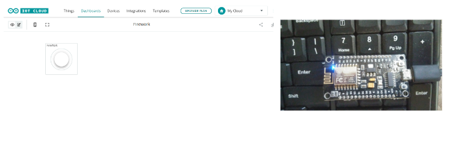
Next we can Add a DashBoard
First for that go to Dashboard tab. And select (Build DashBoard)

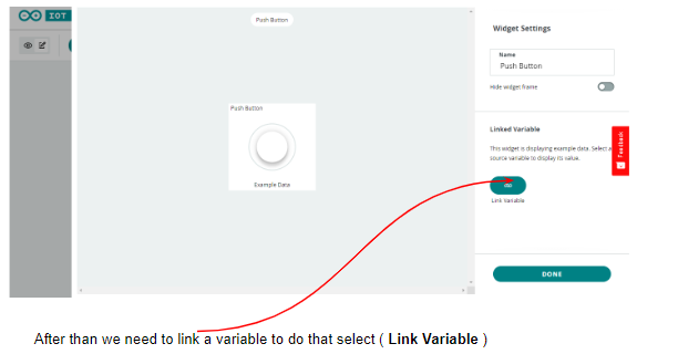
Your Button is Created
When You click the button you can see the LED on the Nodemcu Built in Led Glow,
Connect the relays and Build up the circuit so when you press the button the relay will turn on
When You Download the Arduino iot App and Join with the Same email ID . The switch will appear in the mobile Dashboard too…Instead of arduino iot you can use many the platforms Like BLYNK etc…
This is the End of this Tutorial BYE 😀
While Using this Project make sure that your NodeMCU and other components ( Especially Battery ) Away from the fire crackers