Arduino IOT Cloud with ESP8266 tutorial
In this post we learn how to use Arduino IOT cloud with ESP8266 nodeMCU tutorial to send and receive data over Internet wirelessly.
This is very basic getting started tutorial of Arduino IOT Cloud, this tutorial help us to build more complex IOT projects in future.
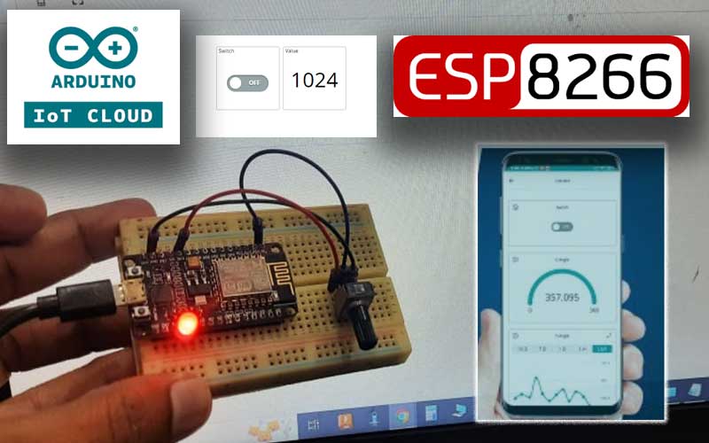
In this project one 5mm Red LED and one potentiometer connected to ESP8266, we will try to turn on LED from Arduino IOT Cloud dashboard also try to receive potentiometer data to Arduino IOT dashboard.
Before starting the tutorial it is very important for us to understand what Arduino IOT cloud actually is.
What is Arduino IOT Cloud ?
Arduino IOT cloud is a web based platform to connect and control multiple devices over internet wirelessly.
If you setup your IOT project on Arduino IOT Cloud then you can control your project from anywhere in the world over internet from PC or mobile APP.
Below is the list Arduino IOT compatible devices, We are using ESP8266 in this tutorial.
- MKR 1000 WiFi
- MKR WiFi 1010
- MKR WAN 1300
- MKR WAN 1310
- MKR GSM 1400
- MKR NB 1500
- Nano RP2040 Connect
- Nano 33 IoT
- Portenta H7
- Portenta H7 Lite Connected
- Nicla Vision
Supported third-party devices can also be used:
- A wide range of Wi-fi enabled ESP32 and ESP8266 based devices. For a list of supported models, go to the Devices tab in IoT Cloud and click “Add”. Then click Set up a 3rd Party device and open the Select model dropdown for ESP32 or ESP8266.
- LoRaWAN® devices
Component used
- Esp8266 nodemcu
- 5mm Red LED
- 10K pot (can use any value)
- Breadboard
- Jumper wires
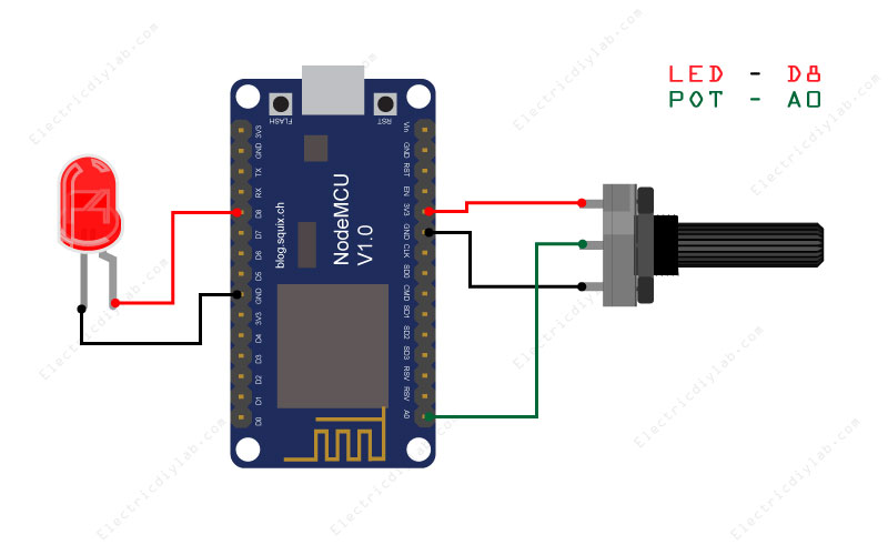
Wiring diagram for Arduino IOT cloud with ESP8266 Tutorial
Our target is to turn ON and OFF LED from Arduino IOT Cloud dashboard and displaying Potentiometer value on the dashboard of Arduino IOT Cloud.
Led and Potentiometer is connect to ESP8266 NodeMcu, below is the wiring diagram please do connection as per the image. by the wiring is very simple just we have to connect one LED and one potentiometer that’s it.
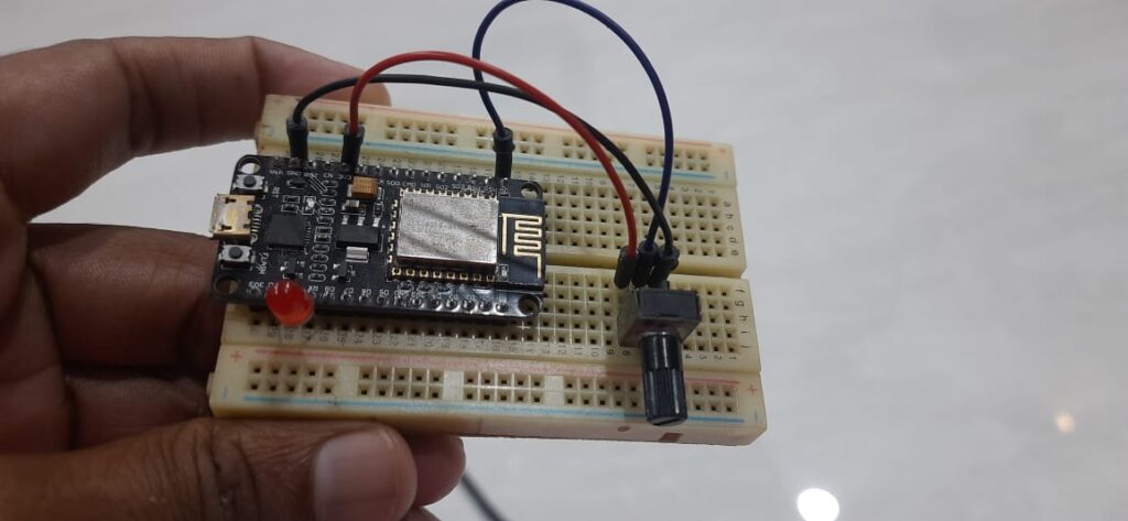
As soon as wiring is done, now its time to do setup for Arduino IOT Cloud so the interesting part begin now.
So lets get start.
Getting started with Arduino IOT Cloud Setup
Few Important things to understand before proceed further.
As long as we use Arduino IOT Cloud all arduino codes are must have to upload arduino IOT Cloud IDE itself.
So in our case ESP8266 or in general any compatible board have to connect with USB cable with the PC and code is to upload from IOT cloud web server, to handle this we first need to install “Arduino create agent” this is only one time installation then it will automatically keeps running in background.
you can Download “Arduino create agent” from here.
How to install Arduino create agent
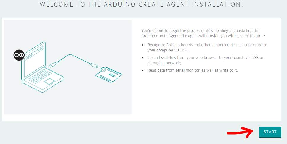
This is the home screen for Arduino create agent simple Click on “START”
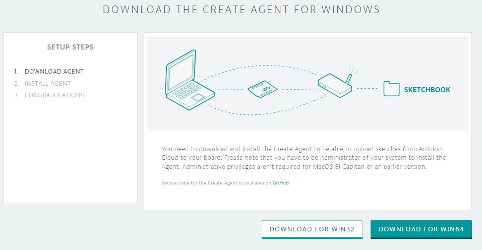
No proceed as per your system Architect
32 bit or 64 bit,
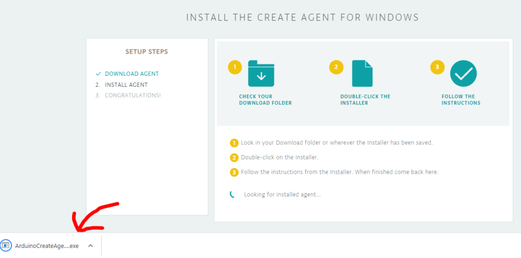
“ArduinoCreateAgent” will Automatically download to the download folder.
As soon as file download launch it and do not close this window till.
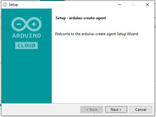
Click next to proceed further
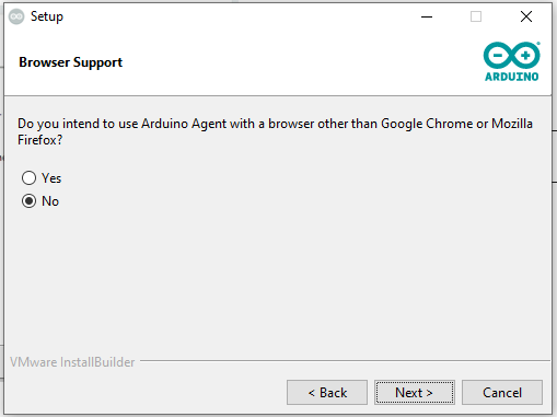
At this page select yes if you use browser for Arduino IOT cloud other then Chrome and Mozilla
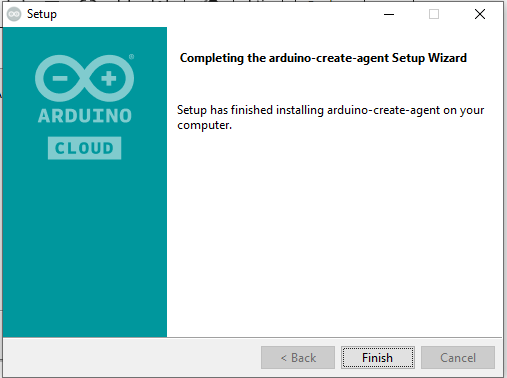
Arduino create agent installation is complete by clicking on Finish and it is already running in back ground.
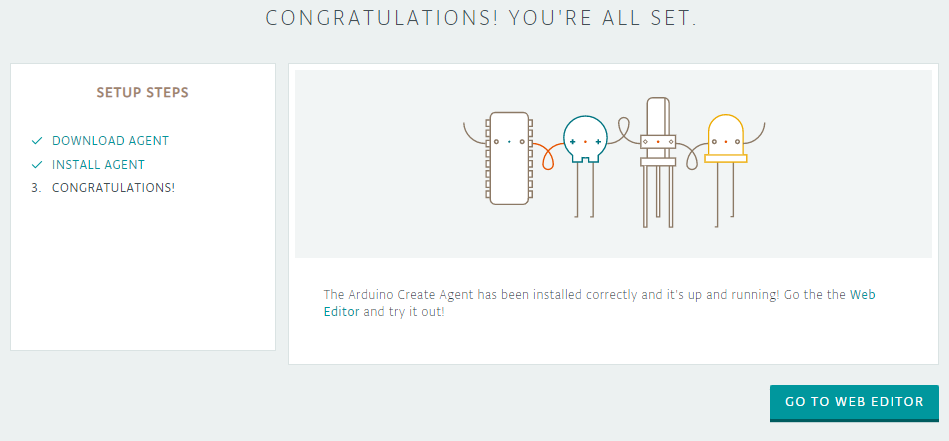
At this point we are ready with Arduino create agent this is the only one time installation, you don’t need this step any more in future as far as arduino create agent is installed in your system.
Now we are ready to move towards Arduino IOT Cloud
How to setup Arduino IOT Cloud setup
Link to visit Arduino IOT Cloud
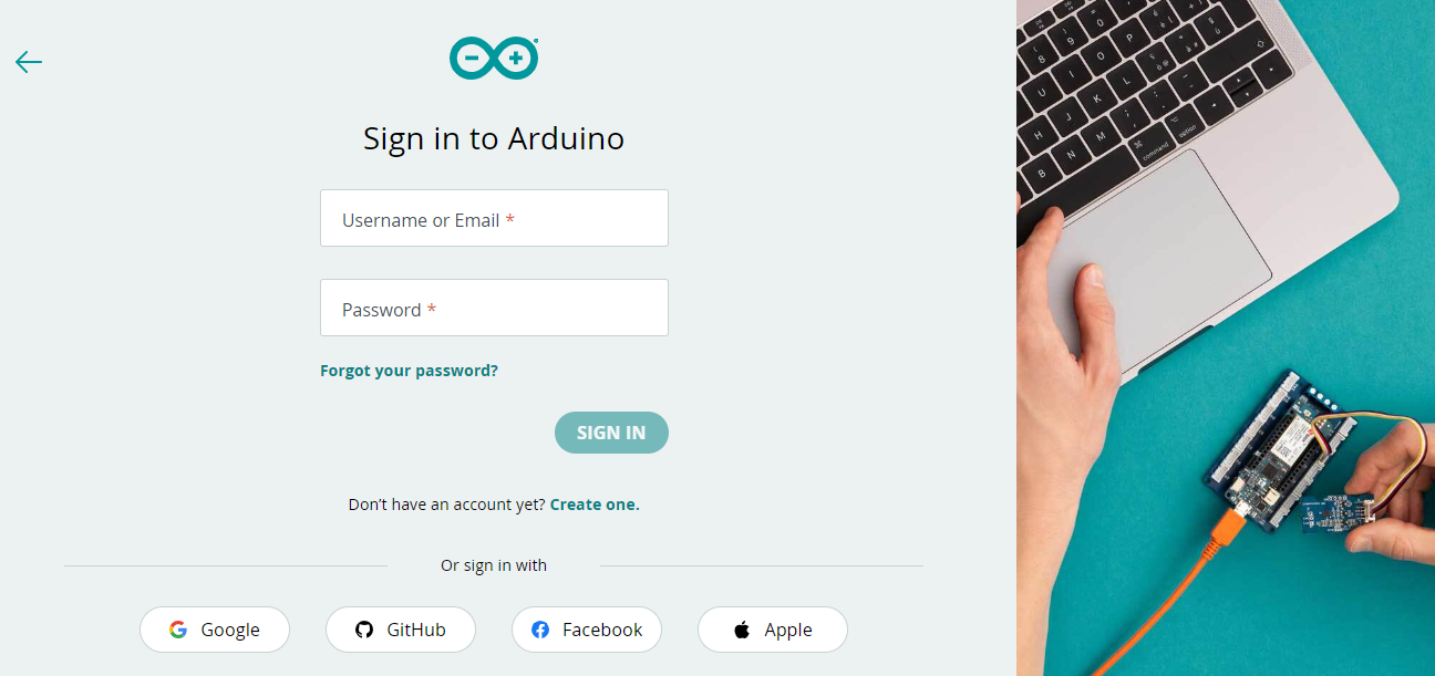
This is the home page of Arduino IOT Cloud you have to login first from here from the option of your choice.
I proceed with my google account.
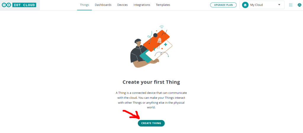
The first step is to create thing by clicking on CREATE THING option.
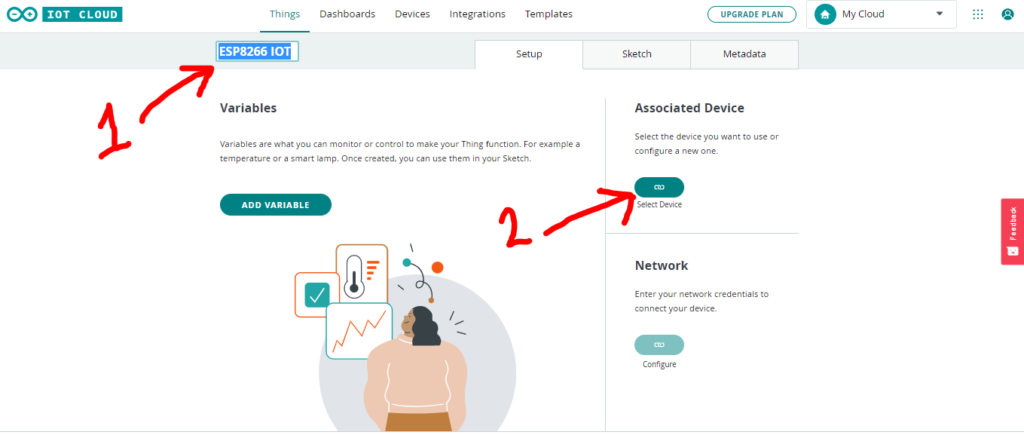
- Give a name to your thing of your choice.
- Now click on link option to select the device.
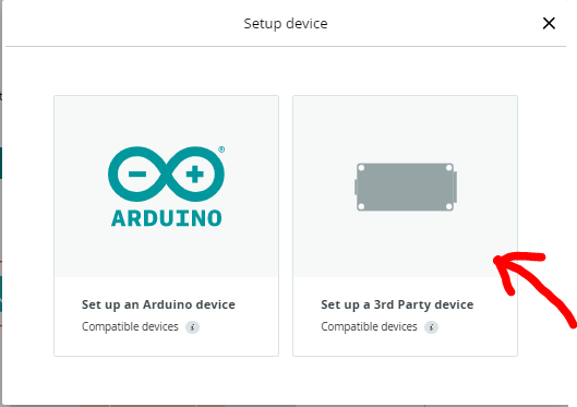
I am using ESP8266 so I am going to select 3rd party device option.
If you are using any Arduino device then you go with Arduino device option.
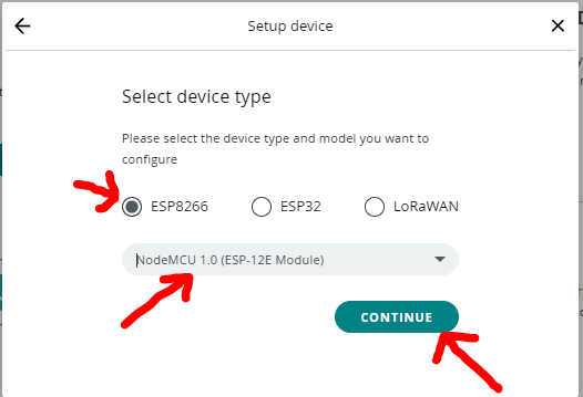
- Select the ESP2866
- Then selecting the type from the drop down option.
- After that click CONTINUE option.
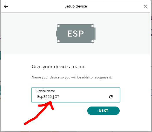
Here we have option to give name to our device.
You can give any name of your choice.
and then click on NEXT
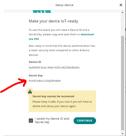
This is very important part you have to copy the secret key we’ll need it later.
past it anywhere so you don’t miss it.
Then click on CONTINUE.
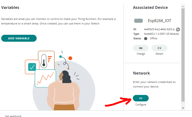
Now in Network option click on link to provide your WIFI credential and device key.
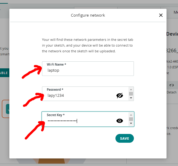
- Enter your WIFI Name
- Enter your WIFI Password
- In last option enter that secret key which we have copied in previous step.
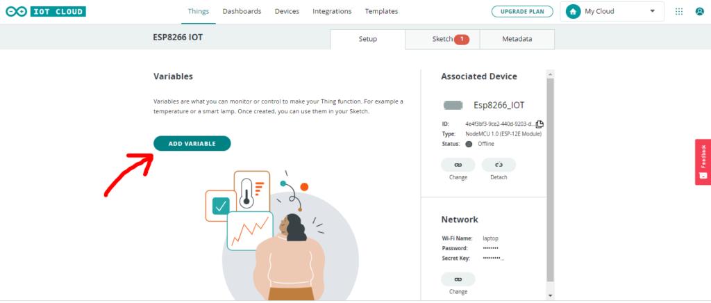
Now we have to add variable by clicking on ADD VARIABLE option
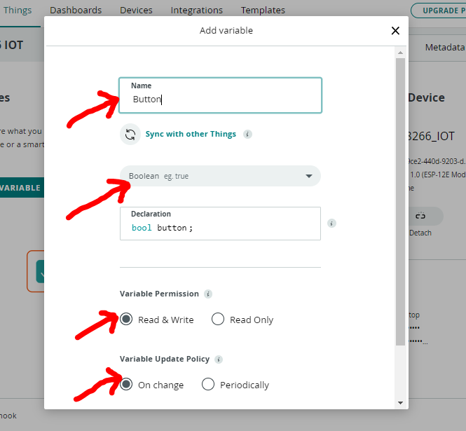
Our first variable is Button which is required to ON/OFF Led connected to Esp8266
I name the variable Button
Data type is Boolean
permission Read & Write
selecting On change as update option
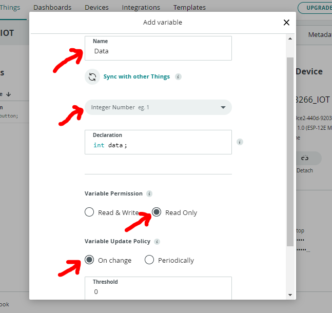
Our second variable is for potentiometer to display data on arduino IOT dashboard.
We name it as Data
data type is Integer
permission is Read Only
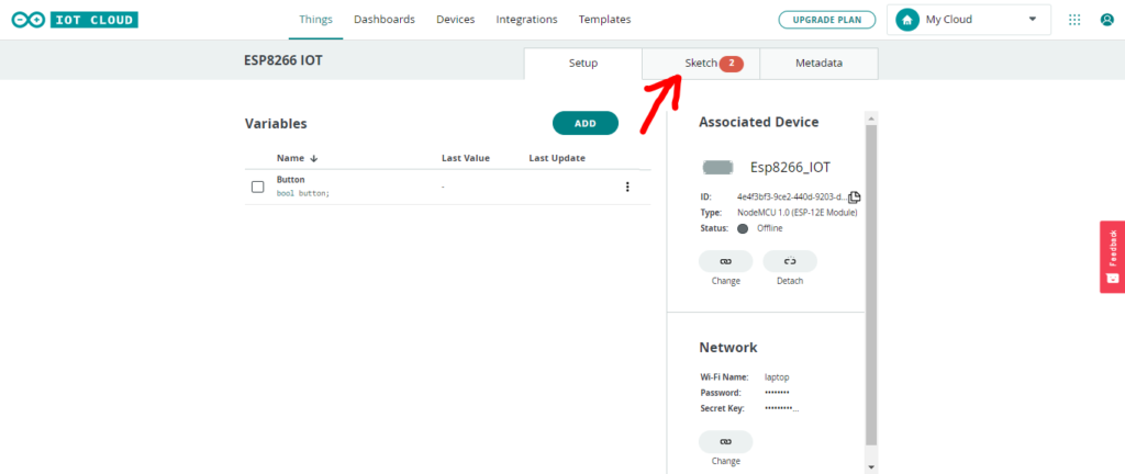
After creating the Variables its time to edit code for that go to the Sketch option.
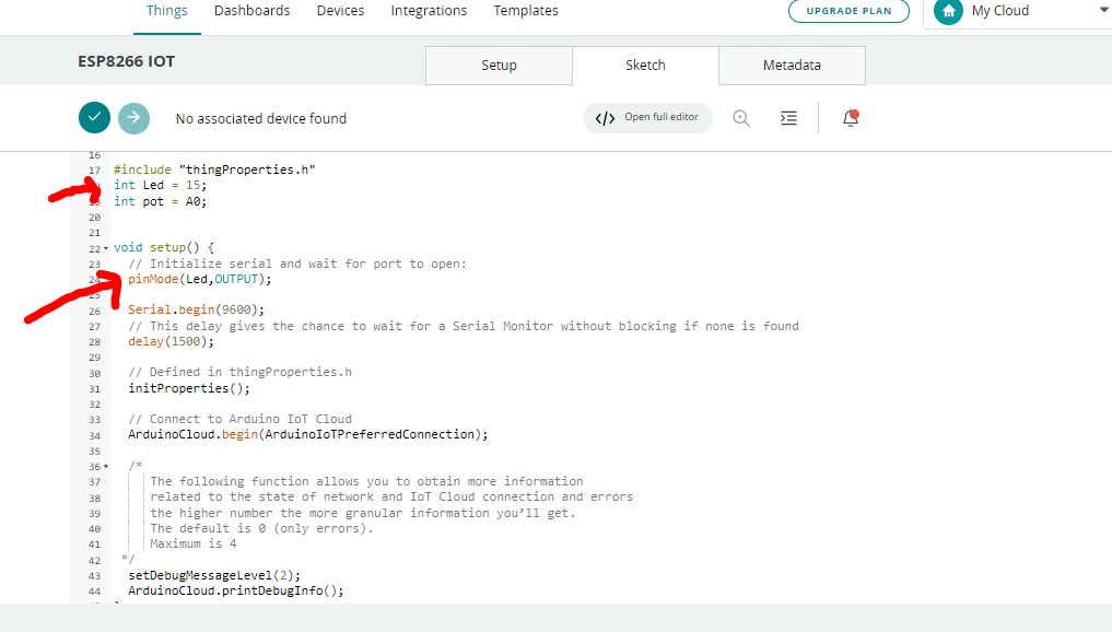
First I have declare the ESP8266 pin numbers of LED and POT at which they are connect.
In setup mode I declare Led as an OUTPUT
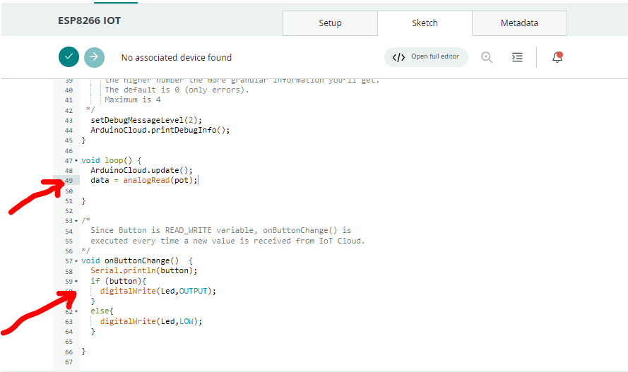
In loop function I declare our variable data as analog read.
So potentiometer value will store in data variable and then it will display on dashboard.
In button change function I read the button state and turn Led ON/OFF according to it.
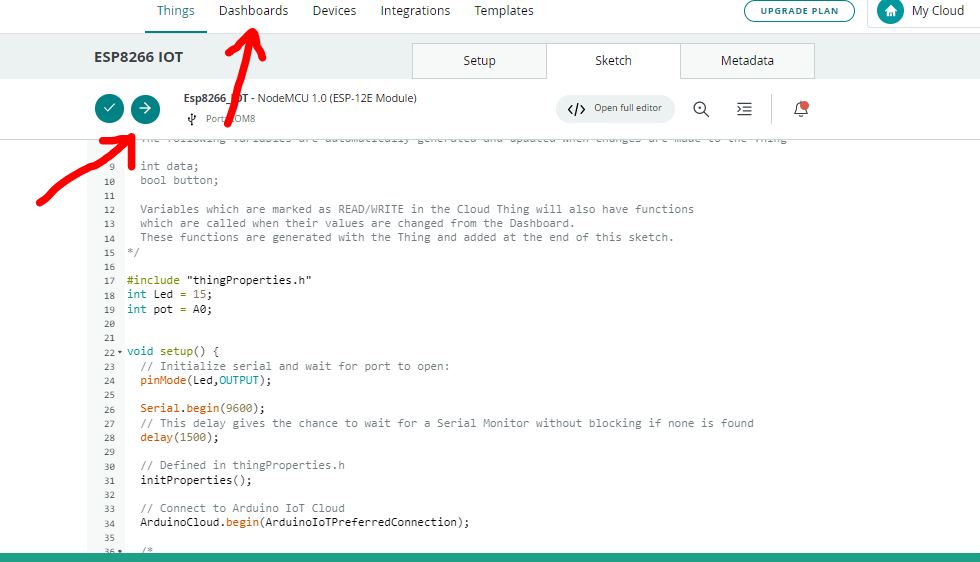
Now we have to connect ESP8266 setup to PC via USB cable and upload the code.
After that click on dashboard to create widget to control components connected to esp8266.
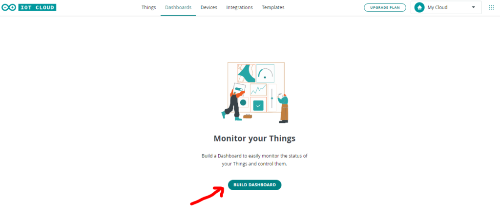
Now click on BUILD DASHBOARD
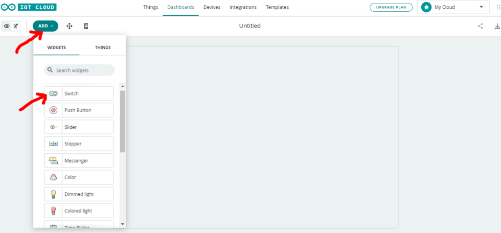
First click on ADD option to add widget.
I am going to select Switch to turn LED ON/OFF
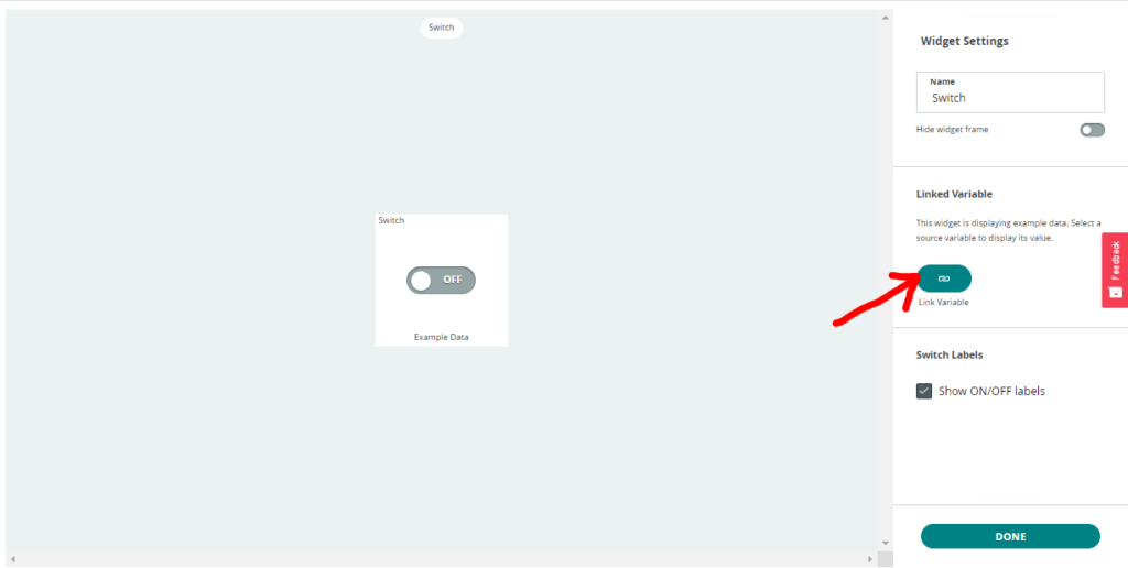
After creating widget we have to link with the variable which we have created earlier.
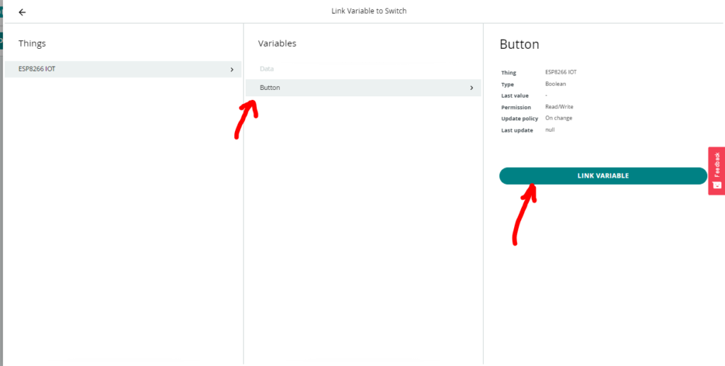
As obvious Switch widget is to link with Button variable.
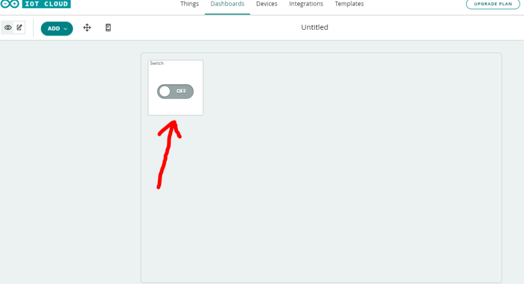
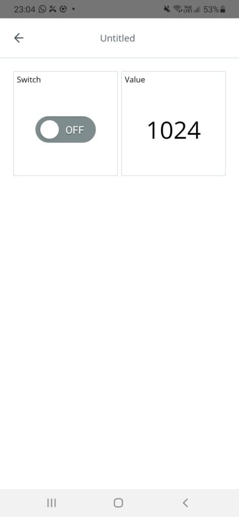
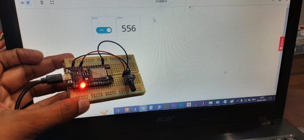
See now a Switch widget is visible on dashboard.
We can turn LED ON/OFF by clicking on this widget.
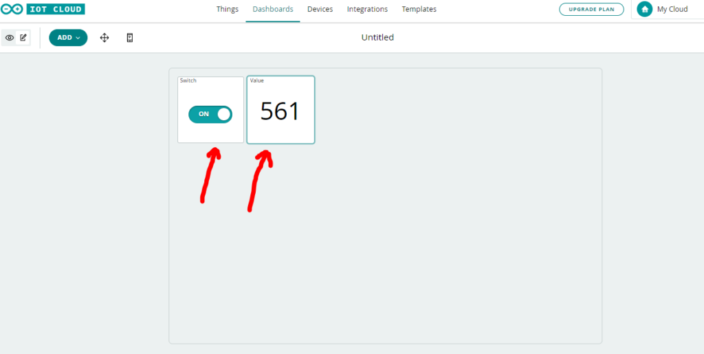
Same as switch widget I select value widget to display to potentiometer data, and link this widget with data variable.
Data from potentiometer will be display on this widget.
So guys in this way we have created a basic Arduino IOT Cloud project.
Now we can send data from IOT dashboard to ESP8266.
and also we can receive data from ESP8266 to IOT dashboard.
By clicking on Switch widget LED will turn ON or OFF and when we rotate knob of potentiometer the correspondence value will display on value widget on dash board.
Video of Arduino IOT Cloud with ESP8266 tutorial
You can also control the component from you mobile just download Arduino IOT Cloud Remote app login with the same account you will readily have same dashboard on your Phone.