Controlling N20 Micro Gear Motor with Encoder using arduino
Hello friends in this post we will learn Controlling N20 Micro Gear Encoder Motor with arduino
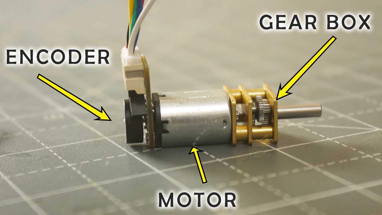
This micro motor have metal gears box directly connected to the output shaft of the motor
in this way this micro looking motor delivery quite high torque comparative to its size.
Such micro metal gear motors come in two models with encoder and without encoders
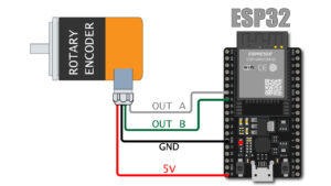
In this post we are going to learn how we can connect the encoder of N20 micro motor and get the rotation feedback to the arduino.
This motor comes in different RPM configuration mine was 75RM

N20 micro gear motor Encoder details
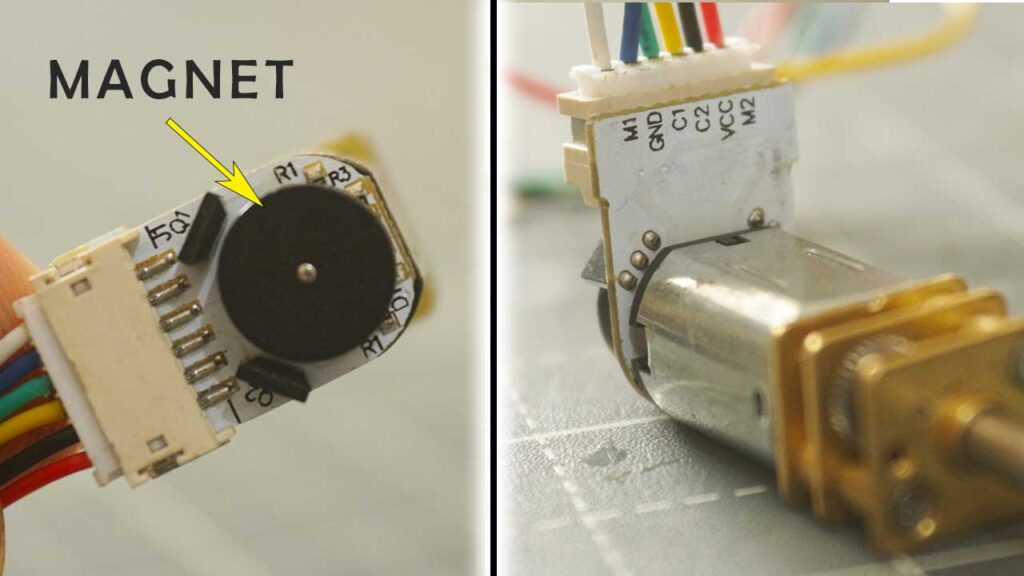
The encoder assembly is fitted on the back side of the motor
the encoder PCB is directly solder to the power terminals of the motor.
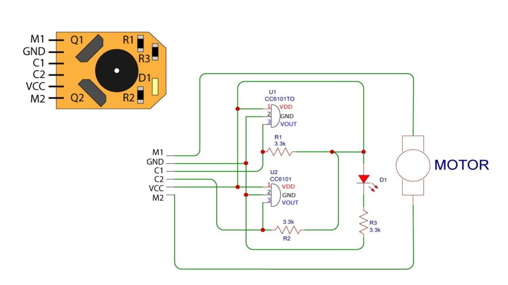
Q1 & Q2 – CC6101 hall effect sensor
R1, R2, R3 – 3.3Kohm Resistor
D1 – LED
Above is the internal circuit diagram of Encoder of N20 micro metal gear motor
as you can see Two C6101 hall effect sensors are placed diagonally to the circular magnet
and this magnet is fixed on the rear shaft of the moto as motor rotates the magnet will also rotate
and hall effect sensor detect the motion of the magnet and generate output at terminal C1 & C2
Terminal details
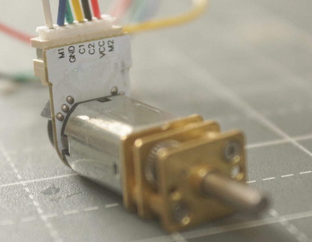
M1 – MOTOR TERMINAL
GND – GND
C1 – ENCODER OUTPUT (A)
C2 – ENCODER OUTPUT (A)
VCC – 5V SUPPLY OF ENCODER
M2 – MOTOR TERMINAL
M1 & M2 – are the motor power terminals the positive and negative supply to this terminal will decide the direction of the rotation of motor
C1 & C2 – this terminal are the output A & B of Encoder
output must connect with arduino.
VCC – is 5V supply of encoder.
GND – is the system ground.
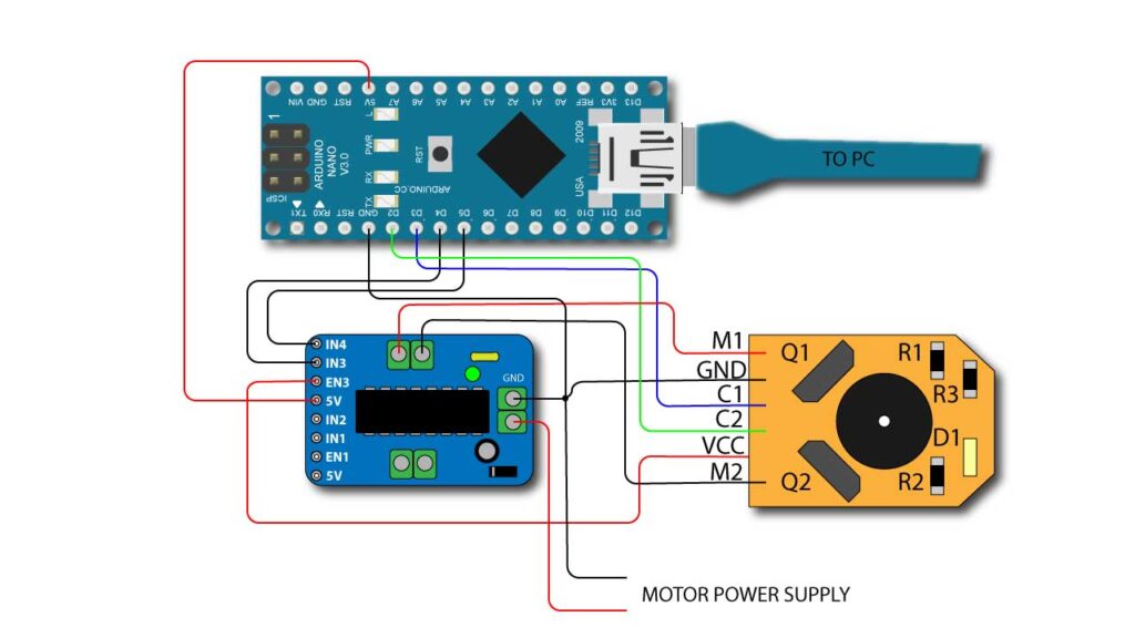
Connection with arduino
Now we will connect our N20 encoder micro gear motor with arduino to do so we need a motor driver we cannot directly connect motor to the arduino pins.
For this we are using L293D motor driver for this purpose .
Arduino Code
below is the arduino code for Controlling N20 Micro Gear Encoder Motor with arduino
#define MotFwd  3  // Motor Forward pin
#define MotRev  4 // Motor Reverse pin

int encoderPin1 = 2; //Encoder Output 'A' must connected with intreput pin of arduino.
int encoderPin2 = 3; //Encoder Otput 'B' must connected with intreput pin of arduino.
volatile int lastEncoded = 0; // Here updated value of encoder store.
volatile long encoderValue = 0; // Raw encoder value


void setup() {

  pinMode(MotFwd, OUTPUT);
  pinMode(MotRev, OUTPUT);
  Serial.begin(9600); //initialize serial comunication

   pinMode(encoderPin1, INPUT_PULLUP);
  pinMode(encoderPin2, INPUT_PULLUP);

  digitalWrite(encoderPin1, HIGH); //turn pullup resistor on
  digitalWrite(encoderPin2, HIGH); //turn pullup resistor on

  //call updateEncoder() when any high/low changed seen
  //on interrupt 0 (pin 2), or interrupt 1 (pin 3)
  attachInterrupt(0, updateEncoder, CHANGE);
  attachInterrupt(1, updateEncoder, CHANGE);


}

void loop() {

for (int i = 0; i <= 500; i++){
digitalWrite(MotFwd, LOW);
 digitalWrite(MotRev, HIGH);
 Serial.print("Forward  ");
 Serial.println(encoderValue);
}

delay(1000);

for (int i = 0; i <= 500; i++){
digitalWrite(MotFwd, HIGH);
 digitalWrite(MotRev, LOW);
 Serial.print("Reverse  ");
 Serial.println(encoderValue);
}

delay(1000);

}

void updateEncoder(){
  int MSB = digitalRead(encoderPin1); //MSB = most significant bit
  int LSB = digitalRead(encoderPin2); //LSB = least significant bit

  int encoded = (MSB << 1) |LSB; //converting the 2 pin value to single number
  int sum  = (lastEncoded << 2) | encoded; //adding it to the previous encoded value

  if(sum == 0b1101 || sum == 0b0100 || sum == 0b0010 || sum == 0b1011) encoderValue --;
  if(sum == 0b1110 || sum == 0b0111 || sum == 0b0001 || sum == 0b1000) encoderValue ++;

  lastEncoded = encoded; //store this value for next time

}
Some explanation about the code.
This code will run motor in Forward direction for some time and then run in Reverse direction meanwhile we can get the encoder value at our Serial Monitor.
When motor moves in forward direction encoder value will increment and if motor moves in reverse direction the encoder value will decrease.
This is very basic code just to get idea how we can get encoder value from the encoder.
In next post we will se how we can perform position control using PID on N20 motor.
Encoder value calculation
Encoder pulse per revolution = 28
so one rotation of output shaft = Encoder pulse per revolution X Gear Ratio
So pulse per one rotation = 28 X 100
= 2800 Pulse per revolution.