How to use GY-271 Magnetic field sensor with Arduino
Hello friends in this article we will learn how we can use GY-271 3-axis magnetic field sensor with arduino.
By using this sensor and arduino board we can build a digital magnetic compass which can indicates the direction liken East, West, North or South.
In this tutorial we will learn how to connect GY-271 3-axis magnetic field sensor module with arduino and getting simple reading on serial monitor.
Applications
Magnetic compass sensor are used in various gadgets infect you also have it in your mobile phone.
also it can be used in robots to get heading information, it also used in self-balancing robots, autonomous cars etc.
Magnetic sensors are used wherever the sense of direction is needed.
GY-271 3-Axis Magnetic field sensor pinout
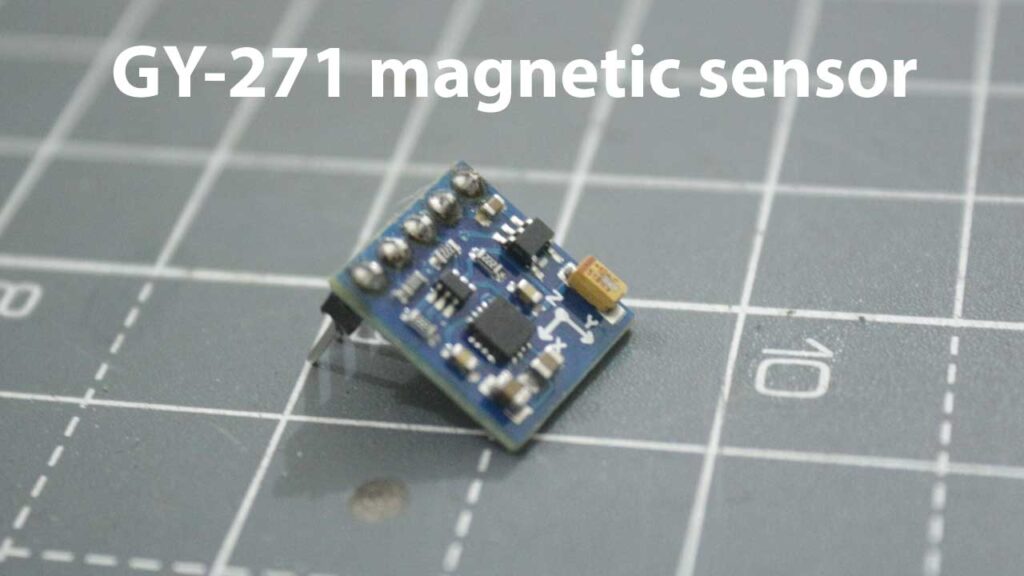
This GY-271 magnetic sensor is loaded with QMC5883L IC which have high resolution of 12 bit ADC its accuracy is somewhat near 1 to 2 degree.
its have on board voltage regulator so you can use voltage laver range from 3.3V to 6V DC.
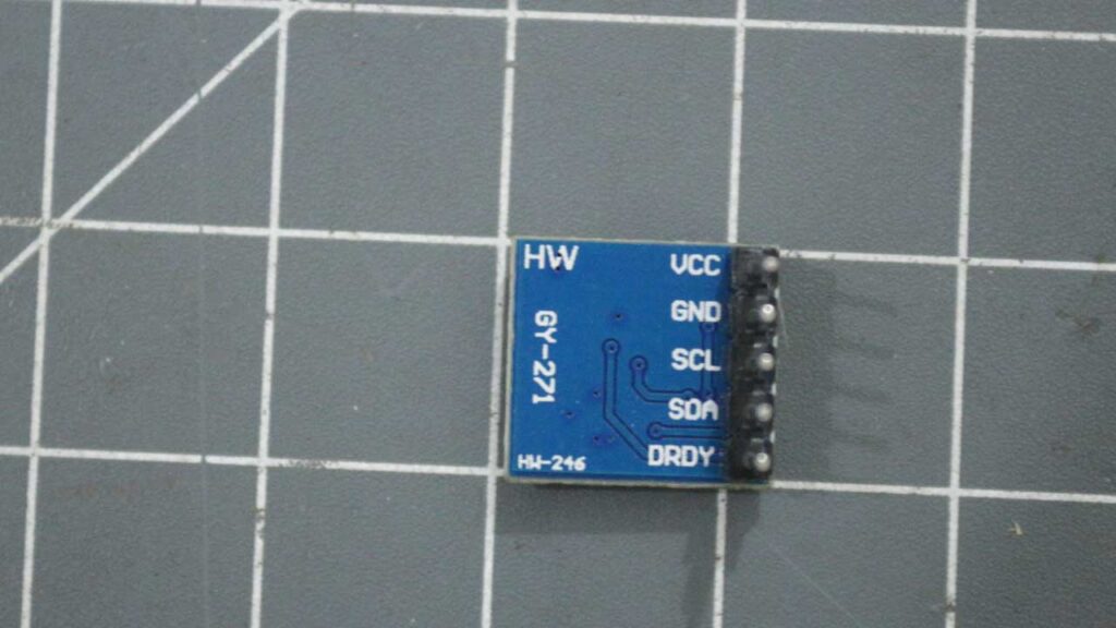
GY-271 sensor have four pins
1. VCC – power supply for module 3.3V to 6V DC
2. GND – Module ground pin
3. SCL – I2C clock pin
4. SDA – I2C data pin
5. DRDY – Data ready this pin will generate a interrupt when output data is available. (generally not used in many of our application).
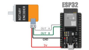
GY-271 Connection with arduino
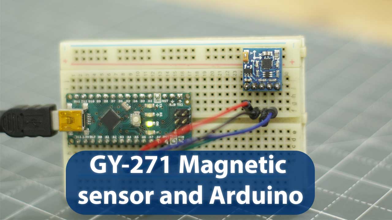
now we are going to connect our GY-271 3-axis magnetic sensor with Arduino so obviously we need a Arduino board I am using Arduino nano, some jumper wires and a bread board.
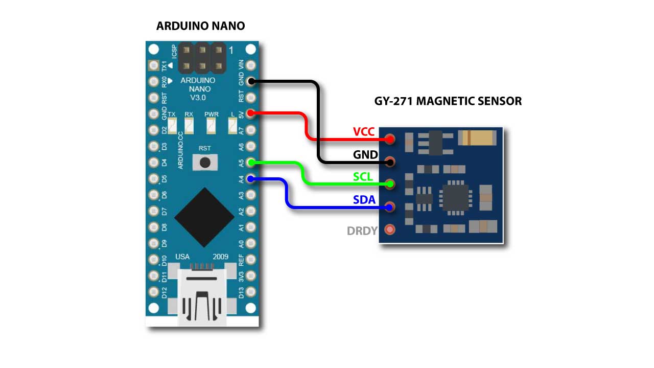
GY-271 connection is very simple just connect the wires as show above.
connect 5V of arduino with VCC of module
connect GND of arduino with GND of module
A5 pin of arduino connect with SCL pin of module
A4 pin of arduino connect with SDA pin of module
Arduino Code
Now we are all set to upload code to arduino so that we can some raw data from the sensors
so first of all we need a library need to install in Arduino IDE
This is the link of HMC5883L_Simple library
please download it and install it to your arduino IDE before proceeding further
Now open the arduino IDE do to
File > Examples > HMC5883L_Simple > compass
now you have a code to you arduino IDE upload this code to arduino
or you can copy past the code directly from here
/*
 *
 * Compass.ino - Example sketch for reading a heading from an HMC5883L triple axis magnetometer.
 *
 * GY-273 Compass Module  ->  Arduino
 * VCC  -> VCC  (See Note Below)
 * GND  -> GND
 * SCL  -> A5/SCL, (Use Pin 21 on the Arduino Mega)
 * SDA  -> A4/SDA, (Use Pin 20 on the Arduino Mega)
 * DRDY -> Not Connected (in this example)
 *
 * Voltage Note
 * ~~~~~~~~~~~~
 * The GY-273 Board has a 3v3 Regulator on it, and the SDA/SCL are pulled up to that so it is OK to
 * use with 5v Arduino's.
 *
 * If you are using any other breakout, or the raw IC, you need to be using 3v3 to supply and signal!
 *
 * Datasheet: http://goo.gl/w1criV
 *
 * Copyright (C) 2014 James Sleeman
 *
 * Permission is hereby granted, free of charge, to any person obtaining a
 * copy of this software and associated documentation files (the "Software"),
 * to deal in the Software without restriction, including without limitation
 * the rights to use, copy, modify, merge, publish, distribute, sublicense,
 * and/or sell copies of the Software, and to permit persons to whom the
 * Software is furnished to do so, subject to the following conditions:
 *
 * The above copyright notice and this permission notice shall be included in
 * all copies or substantial portions of the Software.
 *
 * THE SOFTWARE IS PROVIDED "AS IS", WITHOUT WARRANTY OF ANY KIND, EXPRESS OR
 * IMPLIED, INCLUDING BUT NOT LIMITED TO THE WARRANTIES OF MERCHANTABILITY,
 * FITNESS FOR A PARTICULAR PURPOSE AND NONINFRINGEMENT. IN NO EVENT SHALL THE
 * AUTHORS OR COPYRIGHT HOLDERS BE LIABLE FOR ANY CLAIM, DAMAGES OR OTHER
 * LIABILITY, WHETHER IN AN ACTION OF CONTRACT, TORT OR OTHERWISE, ARISING FROM,
 * OUT OF OR IN CONNECTION WITH THE SOFTWARE OR THE USE OR OTHER DEALINGS IN
 * THE SOFTWARE.
 *
 * @author James Sleeman, http://sparks.gogo.co.nz/
 * @license MIT License
 *
 */

#include <Arduino.h>
#include <Wire.h>
#include <HMC5883L_Simple.h>

// Create a compass
HMC5883L_Simple Compass;

void setup()
{
  Serial.begin(9600);
  Wire.begin();

  // Magnetic Declination is the correction applied according to your present location
  // in order to get True North from Magnetic North, it varies from place to place.
  //
  // The declination for your area can be obtained from http://www.magnetic-declination.com/
  // Take the "Magnetic Declination" line that it gives you in the information,
  //
  // Examples:
  //   Christchurch, 23° 35' EAST
  //   Wellington  , 22° 14' EAST
  //   Dunedin     , 25° 8'  EAST
  //   Auckland    , 19° 30' EAST
  //
  Compass.SetDeclination(23, 35, 'E');

  // The device can operate in SINGLE (default) or CONTINUOUS mode
  //   SINGLE simply means that it takes a reading when you request one
  //   CONTINUOUS means that it is always taking readings
  // for most purposes, SINGLE is what you want.
  Compass.SetSamplingMode(COMPASS_SINGLE);

  // The scale can be adjusted to one of several levels, you can probably leave it at the default.
  // Essentially this controls how sensitive the device is.
  //   Options are 088, 130 (default), 190, 250, 400, 470, 560, 810
  // Specify the option as COMPASS_SCALE_xxx
  // Lower values are more sensitive, higher values are less sensitive.
  // The default is probably just fine, it works for me.  If it seems very noisy
  // (jumping around), incrase the scale to a higher one.
  Compass.SetScale(COMPASS_SCALE_088);

  // The compass has 3 axes, but two of them must be close to parallel to the earth's surface to read it,
  // (we do not compensate for tilt, that's a complicated thing) - just like a real compass has a floating
  // needle you can imagine the digital compass does too.
  //
  // To allow you to mount the compass in different ways you can specify the orientation:
  //   COMPASS_HORIZONTAL_X_NORTH (default), the compass is oriented horizontally, top-side up. when pointing North the X silkscreen arrow will point North
  //   COMPASS_HORIZONTAL_Y_NORTH, top-side up, Y is the needle,when pointing North the Y silkscreen arrow will point North
  //   COMPASS_VERTICAL_X_EAST,    vertically mounted (tall) looking at the top side, when facing North the X silkscreen arrow will point East
  //   COMPASS_VERTICAL_Y_WEST,    vertically mounted (wide) looking at the top side, when facing North the Y silkscreen arrow will point West
  Compass.SetOrientation(COMPASS_HORIZONTAL_X_NORTH);

}

// Our main program loop.
void loop()
{
   float heading = Compass.GetHeadingDegrees();

   Serial.print("Heading: \t");
   Serial.println( heading );
   delay(100);
}
Now you can open your serial monitor and can see the heading data coming from GY-271 sensor.