
How to connect optical rotary encoder with Arduino
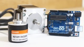
Hello guys in this post we’ll learn how we can connect optical rotary encoder with arduino microcontroller.
First we get some information about what is optical rotary encoder.
VIDEO
You can watch this video or continue to read below post
What is Optical rotary encoder
Optical rotary encoder is a mechanical device having a rotating shaft inside of cylindrical housing, construction look same as motor.
A circular flat disc having two sets of slot on it.
Optical sensors are attached on either sides of this disc, transmitter set on one side and receiver set on one side.
So when slotted disc rotate in between sensor it cuts the optical sensor and signal is generated at receiver ends.
Receiver is further connected with a microcontroller to process generated signal,
in this way we can know how much shaft is rotate.
we can also determine the direction of rotation of shaft by comparing the signal polarity of two outputs. because two sets of slots are at some offset
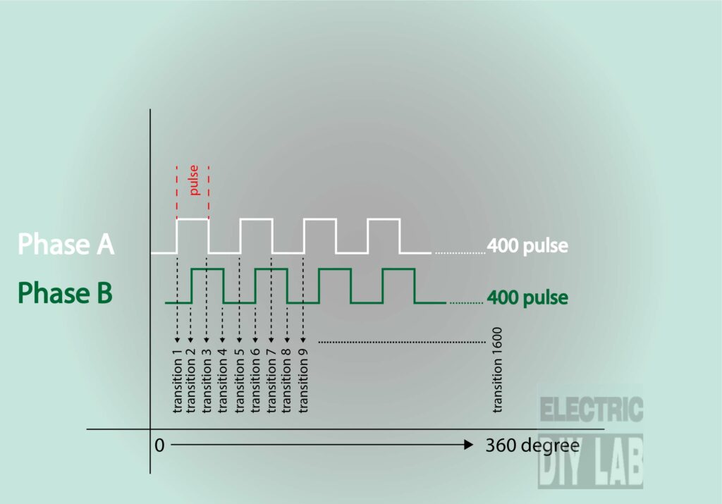
Optical rotary encoder general have two outputs “A” & “B” .
Below is the image to understand how 400 pulse per revolution encoder generate pulse it gives total 1600 transition per revolution. it means it can give very high accuracy.
Types of Encoders
Generally there is Two types encoders
- INCREMENTAL ENCODER
- ABSOLUTE ENCODER
Incremental Encoders
This types of encoders gives pulse as output which can be treated as a incremental signal.
because it doesn’t have any unique vale of any unique position means when power gets off to this encoder it lost its position reference and start with zero.
Absolute Encoders
This types of encoders are more advanced then incremental encoders.
meanwhile they have magnetic disc in place of slotted disc, so it have unique value of each and every position so it can remember its potion also after power off.
In this post we are going to learn about Incremental encoders.
Connection optical encoder with arduino
Here I am using orange make rotary encoder which have 400 pulse per revolution
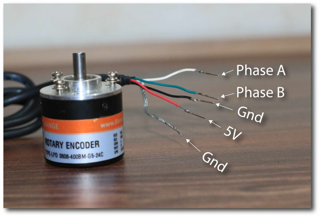
Below you can see the wire details of encoder
WHITE : OUTPU – A
GREEN : OUTPUT – B
BLACK : GND
RED : +5V DC
SHIED : GND
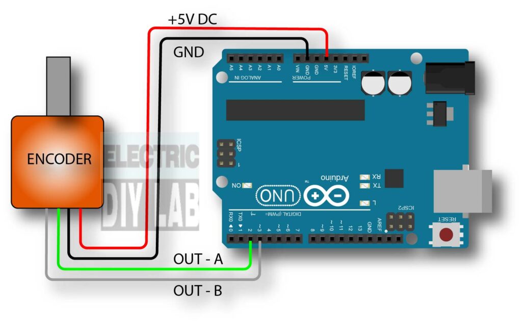
connect optical rotary encoder with arduino as per below
WHITE (OUT A) : PIN 3 (interrupter pin of arduino)
GREEN (OUT B) : PIN 2 (interrupter pin of arduino)
RED : 5V
BLACK : GND
Here we have to note that the output from encoder that is wire green and white must be only connected to interrupt pin of orduino.
otherwise arduino not able to record every pulse from encoder.
you can learn more about interrupt pin on google.
CODE
volatile long temp, counter = 0; //This variable will increase or decrease depending on the rotation of encoder

void setup() {
  Serial.begin (9600);

  pinMode(2, INPUT_PULLUP); // internal pullup input pin 2

  pinMode(3, INPUT_PULLUP); // internalเป็น pullup input pin 3
   //Setting up interrupt
  //A rising pulse from encodenren activated ai0(). AttachInterrupt 0 is DigitalPin nr 2 on moust Arduino.
  attachInterrupt(0, ai0, RISING);

  //B rising pulse from encodenren activated ai1(). AttachInterrupt 1 is DigitalPin nr 3 on moust Arduino.
  attachInterrupt(1, ai1, RISING);
  }

  void loop() {
  // Send the value of counter
  if( counter != temp ){
  Serial.println (counter);
  temp = counter;
  }
  }

  void ai0() {
  // ai0 is activated if DigitalPin nr 2 is going from LOW to HIGH
  // Check pin 3 to determine the direction
  if(digitalRead(3)==LOW) {
  counter++;
  }else{
  counter--;
  }
  }

  void ai1() {
  // ai0 is activated if DigitalPin nr 3 is going from LOW to HIGH
  // Check with pin 2 to determine the direction
  if(digitalRead(2)==LOW) {
  counter--;
  }else{
  counter++;
  }
  }
After uploading code to arduino, open serial monitor
and rotate encoder shaft you can see the value increase if you rotate encoder in clock wise direction, and value decrease if you rotate in counter clockwise direction.
If value are showing reverse means giving -ve value for clockwise motion.
you can reverse the “GREEN” & “WHITE” wire.
By using encoder we have made a cool project please check out it here
This is all for this tutorial hope this tutorial may helpful for you.
awesome, just bought an encoder and needed to test it, your code is perfect in my uno
i upload your code and when i rotate the shaft of encoder some value repeat itself on serial moniter.how i solve such problem. what are the changes need to be made on code so that i can count encoder value serially.
find your site very helpful like me as a beginner. my inquiry is the same as above, can you teach us how to put additional button for set/reset and for increment button, let say by 2, 4, 6, 8 and so on… and count start from zero. the ratio of the encoder will now reduce depends on the set value. thanks.
So, has anyone done this?
See Brainy-Bits youtube vid,, Part 3, the problem is his only works, [POORLY], with a hand encoder, even selecting the speeds is very sus. hopeless with an optical encoder, unfortunately. Part 4 the comments show the code fails.
I cant contact him, despite donating to his cause.f0
I cant write code (yet).
If U can do this, so that its reliable, I would be MOST interested. MUCH time lost investigating this challenge!
very interesting, but i need to run a stepper from a similar optical incremental encoder ,
but also to be able to select a range of evenly spaced speeds (min. 8 speeds) from a switch. [0.25, 0.5, 0.75, Normal, 1.25, 1.5, 1.75, 2x speed]
The setup must not lose any steps prefer generating steps on all encoder transitions, with accurate direction change.
Is this possible.?
Has anyone done this?
yes it is possible